o
p
t
i
m
a
r
o
b
o
t
i
c
s

Make a Call


Make a Call
Blogs
2026 Best EDI Water System How Does It Work?
A modern Edi Water System can produce high-purity water continuously, but the “best” unit depends on the feed water, required quality, and operating conditions. EDI, or electrodeionization, is commonly installed after reverse osmosis. It combines ion-exchange resins with selective membranes and a direct-current field to remove dissolved ions. The EDI Water System Working Principle is straightforward: ions move through membranes into concentrate channels, while the resin helps them travel through the dilute chamber. The electric field also regenerates the resin during operation.
The details matter. In a typical plant, operators check feed conductivity, pressure, flow, and product-water resistivity. If pretreatment is poor, hardness or suspended solids can foul components and shorten service life. A stable reading is useful, but it does not explain every change in performance; trends and alarm history matter too. EDI reduces the need for routine chemical regeneration, yet it is not a maintenance-free box. Feed-water limits, sanitization procedures, and monitoring requirements vary by manufacturer and system design.
For buyers comparing 2026 models, capacity, recovery, energy use, controls, and service access deserve close attention. Ask for performance data at your actual feed-water conditions, not just a headline specification. Small details, such as space to replace a module or reach a sample valve, can affect daily operation. “Best” is a moving target. A carefully sized system may outperform a larger, costlier one, though that decision still needs verification with qualified water-treatment professionals.
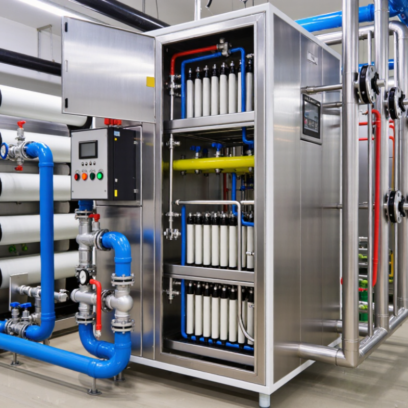
Table of Contents [Hide]
What an EDI Water System Is and How It Fits into Water Treatment
2026 Best EDI Water System How Does It Work?
An EDI water system uses electricity, ion-exchange membranes, and resin to reduce dissolved ions in water. EDI means electrodeionization. In many treatment plants, reverse osmosis removes much of the dissolved material first. The EDI stage then draws remaining charged ions through selective membranes into a separate concentrate stream. The resin helps ions move through the unit, while the electric field continually regenerates it. No routine chemical regeneration is needed, but the system still needs suitable feed water and regular checks.
That matters. EDI is one step in a treatment train, not a complete water-treatment solution. Feed-water quality, pressure, temperature, and flow can affect product quality. Operators often monitor conductivity or resistivity and watch for changing trends. EDI also does not reliably remove every uncharged contaminant or guarantee microbial control. One practical detail is easy to miss: a neat process diagram cannot show every site-specific issue, such as a fouled pretreatment filter. Real systems need real monitoring.
Tips: Check the reverse-osmosis water before it enters EDI, and follow the equipment maker’s operating limits. Record conductivity or resistivity consistently. If readings drift, investigate the feed and operating conditions before assuming the EDI unit itself has failed.
2026 Best EDI Water System How Does It Work? — What an EDI Water System Is and How It Fits into Water Treatment
| System Dimension | How It Works | Typical Feed or Output | Role in Water Treatment | Key Selection or Operating Consideration |
|---|---|---|---|---|
| Feed-water quality | EDI receives low-ion water, most commonly permeate produced by reverse osmosis (RO). | RO permeate; actual limits for conductivity, hardness, silica, carbon dioxide, and other constituents depend on the EDI module. | Provides the controlled feed needed for effective continuous deionization. | Check the module’s feed-water specification and the complete pretreatment design. EDI is generally not intended to treat untreated source water directly. |
| Ion-exchange resin | Resin beads temporarily capture dissolved cations and anions, helping transport ions through the dilute compartment. | Dissolved ionic contaminants in the RO permeate. | Supports ion removal between the membrane barriers. | Feed quality and flow distribution affect performance. Resin does not make EDI a general-purpose filter for suspended solids or organic contaminants. |
| Ion-exchange membranes | Alternating cation- and anion-selective membranes guide positively and negatively charged ions toward concentrate compartments. | Ions migrate out of the product-water stream into a separate concentrate stream. | Separates ionic contaminants from the water being purified. | Membranes are selective for charged species; they do not replace particle filtration or organic-contaminant treatment. |
| Direct-current field | An applied DC electric field drives ion migration through the resin and across the selective membranes. | Electrical power and properly conditioned feed water. | Enables continuous ion removal and helps regenerate the resin during operation. | Voltage, current, temperature, and flow must remain within the equipment manufacturer’s operating limits. |
| Continuous resin regeneration | The electric field splits a small amount of water into hydrogen and hydroxide ions, which help restore the resin’s ion-exchange capacity. | Hydrogen and hydroxide ions are formed within the EDI stack. | Allows the unit to operate continuously without routine chemical regeneration of the EDI resin. | “Chemical-free regeneration” applies to the EDI process itself; the wider water-treatment plant may still use chemicals for pretreatment or cleaning. |
| Dilute and concentrate streams | The dilute stream becomes the purified product, while the concentrate stream carries removed ions away from the stack. | Separate product-water and concentrate-water outlets. | Provides a continuous route for removing contaminants rather than storing them in the product stream. | Concentrate flow, recovery, and disposal or reuse arrangements are system-specific and should be confirmed during design. |
| Product-water quality | EDI reduces dissolved ionic species after RO; performance is monitored using suitable water-quality instruments. | High-purity water; some well-designed systems can produce water approaching 18.2 MΩ·cm resistivity at 25°C under appropriate conditions. | Provides a polishing step for applications requiring low ionic contamination. | Resistivity alone does not establish overall water purity. Silica, boron, dissolved gases, organics, particles, and microbiological quality may require separate monitoring or treatment. |
| Typical process sequence | Common arrangement: pretreatment → RO → EDI → storage and distribution, with additional polishing where the application requires it. | Each stage is selected for the source water and the final quality requirement. | Places EDI after RO as a polishing technology rather than as a standalone treatment train. | Final design depends on source-water analysis, required product-water quality, demand, sanitization needs, and applicable regulations. |
| Monitoring and maintenance | Operators track feed and product quality, flow, pressure, temperature, and electrical readings; pretreatment and instrumentation are maintained. | Routine operating data and water-quality measurements. | Helps identify feed-water changes, scaling or fouling risks, and declining performance. | Use the supplier’s operating and maintenance guidance, and verify product quality with calibrated instruments and appropriate sampling practices. |
Note: EDI performance and operating limits vary by system design, feed-water composition, and application. Confirm specifications with the selected equipment documentation and a qualified water-treatment designer.
Brands
Proudly Trusted by Top Suppliers Worldwide







Let us know and we will automate, together to fit your industrial needs.
 +91-97254 16844
Clients
Proudly Trusted by Top Companies Worldwide


Do you need Help? Get in touch.
X
Please fill out the form below and we will get back to you as soon as possible.