o
p
t
i
m
a
r
o
b
o
t
i
c
s

Make a Call


Make a Call
Blogs
2026 Top Heatsink Thermal Pad Types for Global Buyers
Global buyers entering the 2026 thermal management market need more than a simple list of materials. A Heatsink Thermal Pad must match the device, heatsink surface, pressure, and operating temperature. Small mismatches can create costly hot spots.
Silicone-based gap filler pads remain practical for uneven surfaces and repeated assembly. Ceramic-filled pads can provide electrical insulation with dependable thermal transfer. Graphite pads offer strong in-plane heat spreading, but they may require careful electrical isolation. Phase-change materials can reduce interface resistance after heating, although installation and service conditions need close review. Some newer pads combine compressibility, high conductivity, and low pump-out performance. They sound ideal. They rarely fit every design.
For global purchasing teams, supplier evidence matters. Request thermal conductivity data, thickness tolerance, compression curves, dielectric strength, flammability information, and aging results. Confirm whether testing follows recognized methods, because laboratory values are not always directly comparable. Ask for samples from the same production line, then test them under realistic pressure and temperature cycles. A pad that performs well on a polished test coupon may behave differently against a stamped heatsink.
This guide compares the leading Heatsink Thermal Pad types expected to influence buying decisions in 2026. It considers thermal performance, electrical safety, mechanical compliance, reliability, installation effort, and total cost. Regional availability and documentation quality also deserve attention. A lower unit price may hide higher assembly waste. That assumption often fails. Careful selection remains the safer engineering decision.
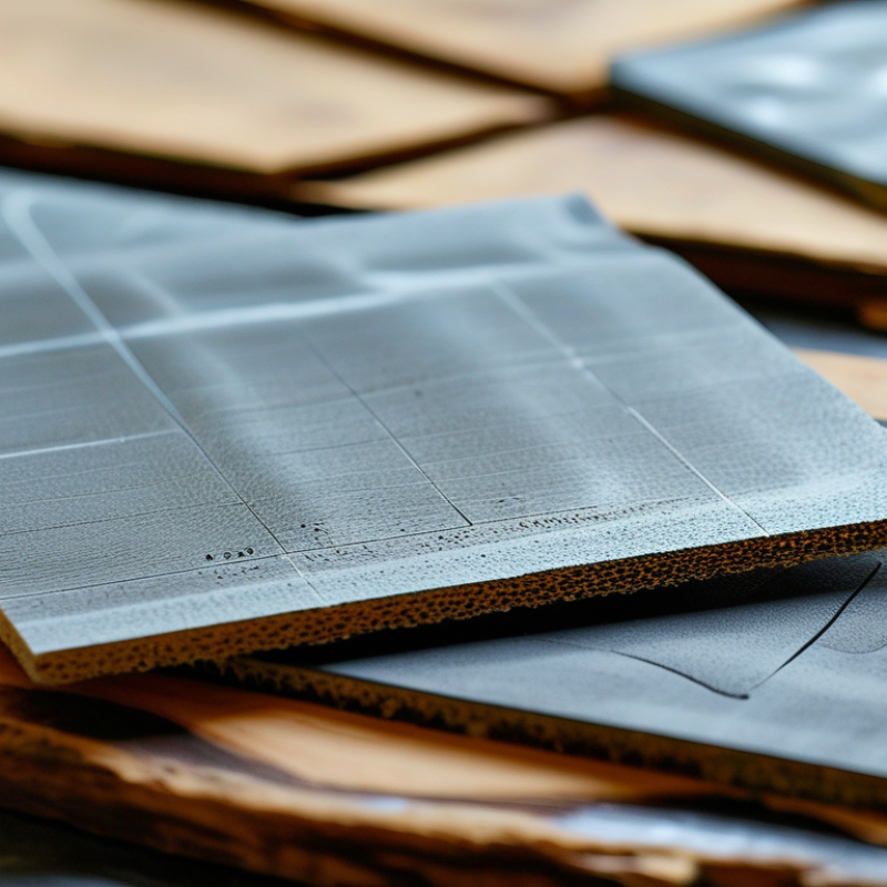
Table of Contents [Hide]
Thermal Pads Explained: Structure, Materials, and Heat Transfer Basics
Thermal pads are compliant interface materials placed between a heat source and a heatsink. Their structure usually combines a flexible polymer matrix with thermally conductive fillers. Common fillers include ceramic particles, aluminum oxide, boron nitride, and graphite. Each material changes conductivity, flexibility, electrical behavior, and long-term stability.
Heat moves through the pad by conduction. The pad fills microscopic air gaps caused by rough metal surfaces. Air transfers heat poorly, so replacing it reduces thermal resistance. Thickness matters too. A thicker pad can bridge a larger gap, but it usually adds resistance. Compression also affects contact quality, especially around uneven components. Fit matters.
Global buyers should check thermal conductivity, thermal impedance, hardness, compression range, insulation rating, and operating temperature. Silicone-based pads often offer strong flexibility and reliable gap filling. Non-silicone options may suit sensitive assemblies, but their handling properties can differ. Graphite-based materials can transfer heat efficiently along selected directions, though electrical conductivity requires careful design. Test data deserves attention. Values measured under different pressure or thickness conditions may not compare fairly.
In practical assembly work, I have seen a highly conductive pad perform poorly because it was compressed unevenly. The specification looked impressive. The installation was not. Cut size, surface cleanliness, storage conditions, and fastening pressure can matter just as much. Some assumptions remain incomplete, particularly when real airflow and enclosure limits are ignored. A small prototype test often reveals more than a catalog number.
Brands
Proudly Trusted by Top Suppliers Worldwide







Let us know and we will automate, together to fit your industrial needs.
 +91-97254 16844
Clients
Proudly Trusted by Top Companies Worldwide


Do you need Help? Get in touch.
X
Please fill out the form below and we will get back to you as soon as possible.