o
p
t
i
m
a
r
o
b
o
t
i
c
s

Make a Call


Make a Call
Blogs
7 Tips for Choosing a Refrigeration Condensing Unit
Choosing the right Refrigeration Condensing Unit affects cooling stability, energy use, maintenance time, and product safety. It is not merely a matter of matching horsepower to a room size. A busy supermarket, a restaurant freezer, and a small cold-storage facility face very different operating pressures.
Danfoss refrigeration expert Kristian Strand has emphasized, “There is no one-size-fits-all solution.” That simple observation deserves attention. A unit that performs quietly in a clean warehouse may struggle beside a hot kitchen exhaust. Ambient temperature, refrigerant type, evaporator capacity, voltage, airflow, and expected load must work together. Ignoring one detail can create frost, high discharge pressure, or repeated compressor cycling.
This guide presents seven practical tips for choosing a suitable unit. It considers capacity, application temperature, efficiency, controls, installation space, service access, and manufacturer support. Each factor matters. Some decisions also involve compromise. A highly efficient model may cost more initially. A compact design may leave less room for technicians. I have seen specifications look perfect on paper, yet fail after dust blocks the condenser coil. That is an uncomfortable reminder: real operating conditions matter more than attractive numbers.
Reliable selection begins with measured information. Record room temperatures, product loads, defrost patterns, and seasonal conditions. Then compare certified performance data, not vague marketing claims. The best choice should provide stable cooling today and practical serviceability years later. Even experienced buyers can overlook small details. That is why careful verification remains essential.
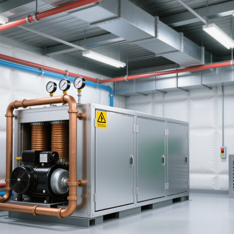
Table of Contents [Hide]
Define the Cooling Load and Operating Conditions
Before choosing a refrigeration condensing unit, define the actual cooling load. Do not rely on room size or compressor horsepower alone. Calculate product load, transmission through panels, door openings, lighting, fans, and people. A freezer receiving warm products needs extra capacity during pull-down. A chilled room has different demands.
Record the design conditions carefully. Include room temperature, target product temperature, evaporating temperature, outdoor ambient temperature, and expected operating hours. A unit selected for 32°C ambient may struggle on a 40°C summer afternoon. Check the refrigerant, voltage, defrost schedule, and required temperature recovery. Small details matter.
I have seen installations work well during normal days but fail after frequent deliveries. The original load estimate missed open-door heat gain. That mistake was expensive. Leave practical capacity for peak conditions, but avoid excessive oversizing. An oversized unit may cycle too often and control humidity poorly. Review manufacturer performance data at the real operating conditions, not only rated conditions. If the load is uncertain, measure temperatures and door activity for several days. Guessing is sometimes unavoidable, but it should be documented and tested.
7 Tips for Choosing a Refrigeration Condensing Unit - Define the Cooling Load and Operating Conditions
Use the following design inputs to compare condensing-unit options. Final selection should be verified against the actual room heat gain, product load, refrigerant properties, local climate, electrical supply, and applicable safety standards.
| Design Dimension | Practical Input or Example | Typical Engineering Reference | Effect on the Condensing Unit | Selection Guidance |
|---|---|---|---|---|
| 1. Total Cooling Load | Calculated room and product load: 8 kW of refrigeration capacity at the specified evaporating and condensing conditions. | Cooling load includes transmission, product pull-down, infiltration, lighting, fans, people, defrost, and other internal heat gains. | The compressor must deliver at least the required net capacity at the actual operating point, not only at a nominal rating condition. | Choose a unit whose published capacity meets the design load after all operating corrections are applied. |
| 2. Design Safety Margin | Add approximately 5–15% only after completing the load calculation. | A margin may cover reasonable uncertainty in usage or weather; excessive oversizing can cause short cycling and poor humidity control. | A larger unit can reduce pull-down time but may cycle frequently when the actual load is low. | Prefer a correctly sized or capacity-controlled unit rather than applying a large blanket safety factor. |
| 3. Evaporating Temperature | Medium-temperature example: −10°C evaporating temperature for a room maintained around 0 to 4°C. | Low-temperature applications commonly operate at lower evaporating temperatures than chilled or fresh-product rooms. | Lower evaporating temperature generally reduces compressor capacity and increases compression ratio and energy use. | Match the unit to the required evaporating range and check capacity at the exact suction condition. |
| 4. Condensing Temperature and Ambient | Air-cooled example: outdoor design ambient 35°C with a condensing temperature selected above ambient according to the condenser design. | Condensing temperature depends on ambient temperature, condenser approach, coil cleanliness, airflow, and control settings. | Higher condensing temperature raises head pressure, increases power input, and usually reduces refrigeration capacity. | Use the highest expected ambient or a project-specific design ambient when checking capacity and motor loading. |
| 5. Refrigerant and Application Range | Specify the approved refrigerant, required evaporating range, condensing range, oil type, and maximum working pressures. | Different refrigerants have different pressure-temperature relationships, mass flow rates, discharge temperatures, and capacity characteristics. | Using an incompatible refrigerant or operating outside the approved envelope can cause unsafe pressure, oil-return, or motor-temperature conditions. | Select only a unit whose compressor, controls, valves, seals, and safety devices are approved for the chosen refrigerant. |
| 6. Operating Schedule and Load Profile | Continuous holding load, intermittent operation, product pull-down, or a mixed profile with frequent door openings. | A system with variable load may require compressor staging, capacity modulation, crankcase heating, or properly configured cycling controls. | The load profile affects cycling frequency, suction stability, defrost recovery, energy use, and equipment life. | Consider capacity control or multiple compressors when the minimum load is substantially below the peak load. |
| 7. Condenser Airflow and Installation | Provide unobstructed airflow, adequate clearance, clean intake air, and discharge air separation from the condenser inlet. | Recirculated hot air, fouled coils, and restricted airflow increase condensing pressure and reduce heat rejection. | Poor installation can make a correctly rated unit operate at higher head pressure and consume more electricity. | Verify clearances, fan direction, coil access, service space, weather exposure, noise limits, and local installation requirements. |
| Electrical Supply | Confirm voltage, phase, frequency, maximum overcurrent protection, starting current, and available fault current. | Common commercial supplies include single-phase or three-phase systems at regional voltage and frequency combinations. | Incorrect electrical configuration may prevent starting, overheat components, or create nuisance trips and unsafe conditions. | Match the nameplate electrical data to the site supply and size protection in accordance with local electrical codes. |
| Capacity Verification | Compare published net refrigeration capacity, input power, and current at the project design point. | Capacity ratings are meaningful only when evaporating temperature, condensing temperature, subcooling, superheat, refrigerant, and frequency are defined. | A unit that appears adequate at a catalog rating point may be undersized at a colder evaporator or hotter ambient. | Request a rating selection at the exact design conditions and confirm that the unit remains within its operating envelope. |
Important: The numerical values shown are representative design examples, not a universal equipment recommendation. A qualified refrigeration engineer should complete the load calculation, piping design, refrigerant safety review, controls selection, and code compliance checks for the specific installation.
Brands
Proudly Trusted by Top Suppliers Worldwide







Let us know and we will automate, together to fit your industrial needs.
 +91-97254 16844
Clients
Proudly Trusted by Top Companies Worldwide


Do you need Help? Get in touch.
X
Please fill out the form below and we will get back to you as soon as possible.