o
p
t
i
m
a
r
o
b
o
t
i
c
s

Make a Call


Make a Call
Blogs
What Is the Best Exhaust Pressure Gauge in 2026?
Choosing the best Exhaust Pressure Gauge in 2026 requires more than comparing dial sizes or attractive displays. The right instrument must show exhaust backpressure accurately, respond quickly, and survive heat, vibration, and daily engine use. A dependable gauge helps reveal restricted diesel particulate filters, overloaded turbochargers, blocked mufflers, and inefficient exhaust systems. Small details matter. A clear scale matters. So does a pressure line that does not melt near the manifold.
Turbocharging specialist Gale Banks is widely associated with the practical warning, “Backpressure is not boost.” That short statement deserves attention. Boost pressure measures air entering the engine, while exhaust pressure shows how hard gases push against the engine’s outlet. These readings can differ sharply. A modern Exhaust Pressure Gauge should therefore offer a suitable pressure range, stable calibration, and easy-to-read markings. Digital models may provide data logging, but mechanical gauges can remain useful because they work without electrical power. Neither type is perfect.
This guide examines accuracy, sensor durability, response time, installation demands, and value. It also considers gasoline and diesel applications separately. A gauge designed for a mild street engine may fail in a high-temperature turbo system. That is easy to overlook. Buyers should check the sender’s temperature rating and connection size before installation. Independent testing and manufacturer specifications deserve more trust than dramatic marketing claims. Even careful recommendations have limits, because engine condition, fuel type, and mounting location change the readings. The best Exhaust Pressure Gauge is not always the most expensive one. It is the one that produces useful information under real operating conditions.
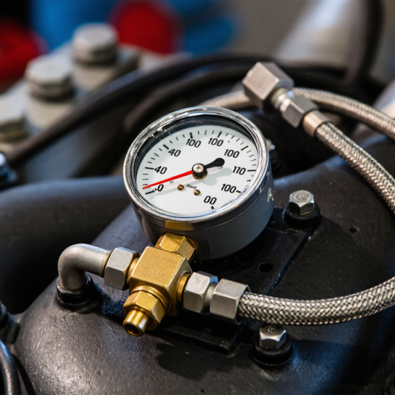
Table of Contents [Hide]
What Is an Exhaust Pressure Gauge and Why Does It Matter?
An exhaust pressure gauge measures the pressure inside an engine’s exhaust system. It is commonly connected before a turbocharger, filter, or catalytic converter. The gauge reveals how hard exhaust gases must work to leave the engine. Low pressure is generally healthy. Rising pressure can suggest restriction, overheating, poor turbo operation, or a damaged component. The warning may appear before noticeable power loss. That makes the gauge valuable for diagnosis, not decoration.
Tips: Choose a gauge with a suitable pressure range, clear markings, and heat-resistant fittings. Check its calibration regularly. Install the sensor away from extreme heat when possible. Always protect your hands and eyes around hot exhaust parts. A careful technician should inspect connections for leaks before trusting any reading.
The best exhaust pressure gauge in 2026 should provide stable readings and respond quickly to pressure changes. Digital displays can be convenient, while mechanical gauges remain simple and dependable. Accuracy matters more than extra features. Compare readings at idle, under load, and during acceleration. Write them down. Patterns often explain more than one number. A pressure reading alone cannot identify every fault, so it should support temperature checks, visual inspections, and manufacturer service data. Even experienced technicians can misread a gauge when the test setup is poor. That is worth remembering.
Brands
Proudly Trusted by Top Suppliers Worldwide







Let us know and we will automate, together to fit your industrial needs.
 +91-97254 16844
Clients
Proudly Trusted by Top Companies Worldwide


Do you need Help? Get in touch.
X
Please fill out the form below and we will get back to you as soon as possible.