o
p
t
i
m
a
r
o
b
o
t
i
c
s

Make a Call


Make a Call
Blogs
China Top Dishwasher Tub Assembly Line Manufacturer?
Choosing a China-based Dishwasher Tub Assembly Line manufacturer requires more than comparing machine prices. The line must handle sheet forming, seam joining, leak testing, and precise tub transfers without creating bottlenecks. A buyer should inspect fixture accuracy, guarding, changeover time, and the way rejected parts are tracked. Ask to see a sample tub move through the actual process. Look closely at the weld area and listen for irregular vibration. Small details matter.
Manufacturing engineer Daniel Wu offers this illustrative viewpoint, not a verified published quotation: “A reliable tub line is measured not only by its output, but by how consistently it controls forming, joining, and inspection.” Treat that as a useful question for supplier discussions, rather than a substitute for documented performance data. Request cycle-time records, quality results, commissioning plans, and references from comparable installations. A polished factory tour is helpful, but it cannot prove long-term uptime. That deserves a closer look.
This article explores how to assess Chinese manufacturers, compare automation levels, and review technical support before investing. It also considers customization, spare parts, and project risks. Some lines look efficient on paper yet struggle with product changes or uneven material flow. No supplier is perfect. A careful comparison should make those limits visible, not hide them behind impressive production claims.
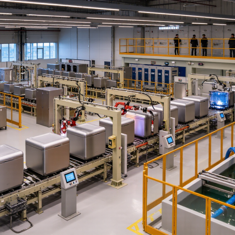
Table of Contents [Hide]
What Is a Dishwasher Tub Assembly Line?
A dishwasher tub assembly line is a coordinated production system for forming, joining, and inspecting the machine’s inner cabinet. The tub usually begins as stainless steel sheet or coated metal. Presses shape the panels through stamping and deep drawing. Trimming removes excess edges. Forming tools create channels for racks, seals, and drainage components.
The line then uses fixtures to position each part accurately. Robotic or semi-automatic welding joins the tub sections. Controlled pressure and heat help prevent distortion. Operators inspect welds, corners, and sharp edges during production.
Sealing equipment applies protective material around selected joints. Even a small gap can cause leakage later. That detail deserves careful attention.
A reliable line includes leak testing, dimensional checks, and barcode-based traceability. Sensors can monitor temperature, force, cycle time, and fixture position. Vision systems may detect incomplete welds or surface defects. In practical factory evaluations, maintenance access matters as much as speed. A fast line becomes expensive when technicians cannot reach a sensor safely. No line is perfect. Misalignment, worn dies, and unstable material thickness still create problems. Regular calibration and sample testing reduce these risks. Quality records should connect each tub with its process data. That evidence supports consistent production and more credible supplier evaluations.
Brands
Proudly Trusted by Top Suppliers Worldwide







Let us know and we will automate, together to fit your industrial needs.
 +91-97254 16844
Clients
Proudly Trusted by Top Companies Worldwide


Do you need Help? Get in touch.
X
Please fill out the form below and we will get back to you as soon as possible.