o
p
t
i
m
a
r
o
b
o
t
i
c
s

Make a Call


Make a Call
Blogs
How to Choose a Cleanroom Dehumidifier in 2026?
Choosing a Cleanroom Dehumidifier in 2026 is not simply an equipment-shopping task. It is a moisture-control decision tied to product quality, energy use, and process stability. A polished specification can still fail when real operating conditions are ignored.
Dr. William P. Bahnfleth, Ph.D., an ASHRAE Fellow and respected HVAC humidity-control authority, offers a useful principle: “Humidity control is a load problem before it is an equipment problem.” This idea should guide every cleanroom evaluation. Engineers need to examine outdoor air, door openings, personnel movement, washing processes, exhaust systems, and seasonal weather. A room near a loading dock may face sudden moisture spikes. A pharmaceutical suite may need stable dew points throughout long production shifts. Numbers matter.
The right Cleanroom Dehumidifier should match the required dew point, airflow, filtration strategy, and heat-recovery plan. Desiccant systems may suit very low dew points, while other applications may benefit from cooling-based control. Capacity alone is not enough. Oversizing can create unstable cycling, unnecessary heat, and higher operating costs. Undersizing may leave condensation risks near cold surfaces.
Reliable selection also requires field experience. Review trend data, not just design assumptions. Check sensor placement beside doors, return-air paths, and critical equipment. Ask how the unit behaves during maintenance and partial-load operation. Some decisions remain uncertain until the room is measured under production conditions. That is an uncomfortable truth, but ignoring it is worse. The best choice balances validated data, practical service access, contamination control, and realistic 2026 efficiency goals.
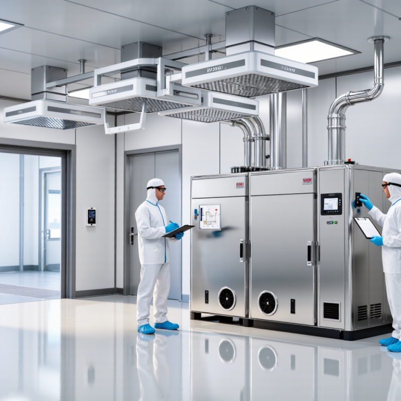
Table of Contents [Hide]
What a Cleanroom Dehumidifier Does and Why It Matters
A cleanroom dehumidifier removes excess water vapor from controlled air. It helps maintain stable relative humidity and dew point levels. This control protects sensitive materials, powders, electronics, coatings, and sterile processes. Moisture can encourage microbial growth on unsuitable surfaces. It can also increase corrosion, condensation, and static-related production errors. Dry air matters.
A suitable unit must match the room’s actual moisture load. Consider outdoor air leakage, door openings, washing procedures, occupancy, and process equipment. Desiccant systems often perform well at low humidity targets. Refrigerant systems may suit moderate conditions with higher room temperatures. The choice depends on the process, not a sales label. Check airflow patterns carefully. The unit should support uniform conditions without disturbing pressure relationships. Sanitary surfaces, accessible filters, sealed construction, alarms, and documented calibration also deserve attention. A cleanroom engineer should verify capacity and integration with the existing HVAC system.
A common mistake is selecting capacity from floor area alone. That approach can leave a room damp during a busy shift. It may also create unnecessary energy use. Review trend data from humidity sensors, especially after cleaning and frequent door traffic. Sensors need suitable placement and regular calibration. Do not assume a dehumidifier removes contamination; it controls moisture only. Performance can change when filters load or operating schedules shift. That uncomfortable detail is easy to overlook. Yet it often explains unstable readings and process complaints.
Brands
Proudly Trusted by Top Suppliers Worldwide






Let us know and we will automate, together to fit your industrial needs.
 +91-97254 16844
Clients
Proudly Trusted by Top Companies Worldwide


Do you need Help? Get in touch.
X
Please fill out the form below and we will get back to you as soon as possible.