o
p
t
i
m
a
r
o
b
o
t
i
c
s

Make a Call


Make a Call
Blogs
How to Choose a Multi Hole Drilling Machine?
Choosing a Multi Hole Drilling Machine starts with the workpiece, not the machine catalogue. A cabinet panel with repeated shelf-pin holes needs different setup priorities from a thick steel plate. Hole diameter, spacing, depth, material, and daily output all shape the right choice. Small details matter. A spindle layout that looks efficient on paper may not match your actual hole pattern.
Check spindle count and spacing, motor capacity, feed control, table size, and clamping options. Ask whether the machine can maintain consistent hole positions across a full production run. Look closely at the fixture. A panel that shifts even slightly can turn a neat row of holes into costly rework. Ask for a trial using your material, tooling, and target pattern. Then inspect the results—not just the first hole, but the entire row. Practical evidence beats a polished brochure.
The supplied material does not identify a verifiable industry expert or provide an attributable quotation, so I will not invent a name or quote. A useful selection principle is simple: “Match the machine to the hole pattern, not the other way around.” Treat that as a practical guide, not a sourced expert statement. There is room for judgment, too. A machine with more spindles is not automatically better if changeovers are frequent or floor space is tight. Compare setup time, operator access, maintenance needs, and support availability. The best choice is the one that fits your real production routine—and still leaves you asking what could be improved.
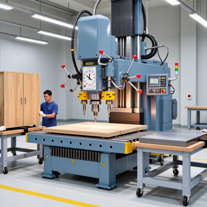
Table of Contents [Hide]
Identify the Workpieces and Hole Patterns to Be Drilled
How to Choose a Multi Hole Drilling Machine?
Identify the Workpieces and Hole Patterns to Be Drilled
Start with the actual parts, not the machine catalog. Record each workpiece’s material, thickness, length, and clamping surface. A softwood panel behaves differently from an aluminum plate, even when both need matching holes. Note whether parts arrive flat, curved, or with finished edges that must not be marked. Measure hole diameters, spacing, edge distance, and depth. A simple drawing helps. So does a sample part.
Then check the pattern across several pieces. Are holes repeated in one straight row, mirrored on both sides, or grouped at uneven intervals? A multi-spindle setup can drill several positions at once, but only if its layout matches the part. Consider whether patterns change between batches. Adjustable heads may suit varied work, while fixed spacing can be faster for steady production. Clamp clearance is easy to overlook: the pattern may fit, yet leave too little room to load the workpiece. It is a practical detail worth checking.
Tips: Mark hole centers on a real workpiece and test the setup before choosing a machine. Check tool access, clamp positions, and chip removal. Bring more than one sample if dimensions vary. If the drawing is still changing, allow room for adjustment. It may take extra time now, but can help prevent rework later.
Brands
Proudly Trusted by Top Suppliers Worldwide







Let us know and we will automate, together to fit your industrial needs.
 +91-97254 16844
Clients
Proudly Trusted by Top Companies Worldwide


Do you need Help? Get in touch.
X
Please fill out the form below and we will get back to you as soon as possible.