o
p
t
i
m
a
r
o
b
o
t
i
c
s

Make a Call


Make a Call
Blogs
How to Choose the Right Tapered Motor Shaft?
Choosing the right Tapered Motor Shaft begins with more than matching a catalog diameter. Torque, rotational speed, taper angle, keyway design, and mounting space must work together. A shaft that fits the motor may still create vibration, slippage, or premature bearing wear.
Richard G. Budynas, a respected mechanical-design authority, writes, “A shaft is a rotating member, usually of circular cross section, used to transmit power or motion.” This principle remains practical when evaluating tapered designs. The shaft must transfer power reliably while maintaining accurate alignment under real operating loads. Measure the bore, exposed length, shoulder position, and allowable runout. Even a small dimensional error can become visible at high speed.
Look closely at the working environment. Dust, moisture, heat, and frequent reversing can change the best material or surface treatment. A hardened steel shaft may suit heavy torque, while stainless steel can be more appropriate near corrosive washdown areas. Do not ignore installation details. A clean taper, correct locking hardware, and proper torque can prevent costly movement during operation.
The perfect choice rarely exists. Trade-offs remain. A larger shaft may improve strength but reduce available clearance. A tighter fit may improve stability but complicate maintenance. This guide examines each decision with practical measurements, engineering reasoning, and realistic limitations, helping readers choose a Tapered Motor Shaft that performs reliably beyond the specification sheet.
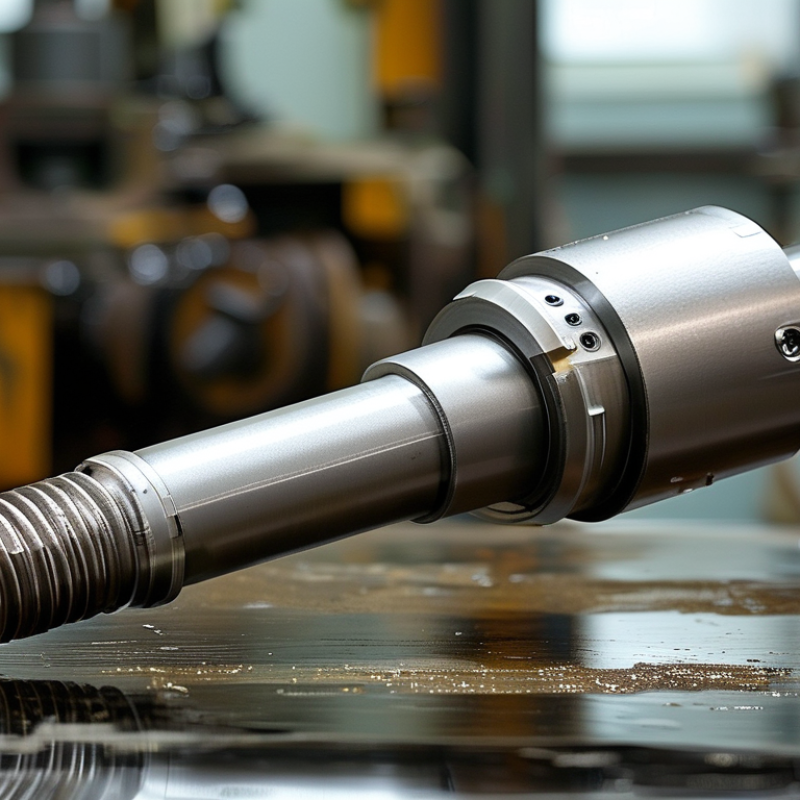
Table of Contents [Hide]
Define Load and Duty: IEC 60034-1 Ratings and S1 Continuous Operation
How to Choose the Right Tapered Motor Shaft?
A tapered motor shaft should match the real load, not only the catalog power. Record torque, speed, starting frequency, inertia, and radial or axial forces. These details influence shaft stress and bearing life. In field checks, I often find that the coupling fits correctly, but the actual load exceeds the original estimate. That mistake is expensive.
IEC 60034-1 ratings provide a consistent basis for evaluating motor performance under stated operating conditions. Check rated voltage, frequency, output power, temperature rise, and installation conditions. S1 means continuous duty. The motor runs at a constant load long enough to reach thermal equilibrium. A conveyor running for eight hours may require a different selection than a mixer starting every few minutes. Do not assume identical power ratings provide identical thermal margins.
Measure twice. Then verify the duty.
For a tapered shaft, confirm the taper angle, shaft diameter, key dimensions, hub contact, and allowable overhung load. A loose fit can create fretting marks near the shoulder. An oversized coupling can increase bending stress, even when torque remains within the rating. Consider the worst operating point, including low-speed cooling and frequent starts.
I would also review the calculation after installation, because measured current and vibration sometimes challenge the design assumptions. That reflection is useful, not embarrassing. Reliability improves when the IEC rating, S1 duty, and mechanical shaft loads describe the same real application.
Brands
Proudly Trusted by Top Suppliers Worldwide







Let us know and we will automate, together to fit your industrial needs.
 +91-97254 16844
Clients
Proudly Trusted by Top Companies Worldwide


Do you need Help? Get in touch.
X
Please fill out the form below and we will get back to you as soon as possible.