o
p
t
i
m
a
r
o
b
o
t
i
c
s

Make a Call


Make a Call
Blogs
How to Choose Weld Fixture Tooling in 2026?
Choosing Weld Fixture Tooling in 2026 means balancing part accuracy, production speed, and the realities of your shop floor. A fixture must hold components securely, maintain repeatable joint alignment, and leave enough access for the welding process. It also needs to suit the part’s size, material, expected production volume, and changeover frequency. Fit matters.
Start with the weldment, not the catalog. Review drawings, tolerances, clamp locations, heat exposure, and the sequence operators will follow. Check whether the tooling can accommodate the welding torch, cables, and inspection equipment without awkward repositioning. For a small batch, adjustable tooling may justify its extra setup time. For steady production, dedicated locating points can support faster, more consistent loading. The best choice depends on actual cycle data, not assumptions.
Material and construction deserve close attention. A heavy fixture can resist movement, but excessive mass may slow handling and complicate maintenance. Replaceable wear surfaces, accessible clamps, and clear datum points can make daily use less frustrating. Yet no checklist predicts every distortion pattern. Trial welds, dimensional checks, and operator feedback reveal what drawings alone may miss. Record those results and revise the setup where needed. Sometimes the first fixture works, but not quite well enough.
This guide explains how to compare fixture types, assess accuracy and flexibility, and plan for safety, maintenance, and future product changes. Its aim is practical: help you choose tooling that supports reliable weld quality without adding needless complexity.
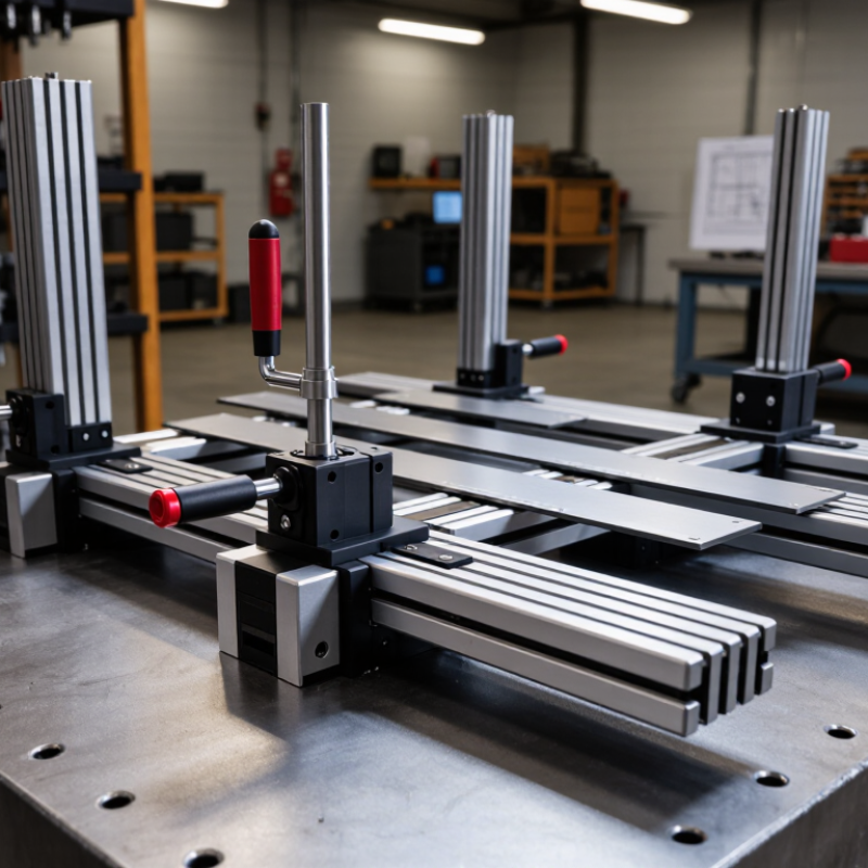
Table of Contents [Hide]
Define Part Geometry and Tolerance Needs Using ISO 13920
ISO 13920 provides general tolerances for welded constructions when individual dimensions lack specific limits. Its tolerance classes cover linear and angular dimensions, plus selected geometric characteristics. The drawing should identify the applicable class and any tighter, function-critical limits. Do not treat the standard as a substitute for defining how mating parts must fit.
Start fixture design with the part’s functional datums: perhaps a machined mounting face, two locating holes, and a welded edge. Relate clamp and support points to those datums, then check the tolerance stack between them. A class suited to a broad frame may be too loose for a close-fitting bracket. Conversely, unnecessarily tight limits can increase machining and inspection effort without improving assembly. Use the current applicable edition and verify class selection against the drawing and production needs.
Weld heat changes geometry. A fixture can hold parts in position, but it cannot erase poor fit-up or predict every distortion. Check sample parts after welding and cooling, measuring the critical interfaces rather than relying only on fixture dimensions. A small gap at a locating pin may reveal more than a perfect-looking setup. Sometimes the first fixture needs adjustment; that is useful evidence, not a design failure.
Brands
Proudly Trusted by Top Suppliers Worldwide







Let us know and we will automate, together to fit your industrial needs.
 +91-97254 16844
Clients
Proudly Trusted by Top Companies Worldwide


Do you need Help? Get in touch.
X
Please fill out the form below and we will get back to you as soon as possible.