o
p
t
i
m
a
r
o
b
o
t
i
c
s

Make a Call


Make a Call
Blogs
How to Choose the Right 2510 Connector?
Choosing the right 2510 Connector begins with more than comparing product photos. In many catalogs, “2510” describes a 2.54 mm pitch family, but naming practices can vary between manufacturers. Confirm the datasheet before placing an order. A connector that looks identical may use different terminals, housings, or locking features.
This guide explains how to evaluate a 2510 Connector for real operating conditions. Check the number of positions, rated current, voltage, wire size, insulation material, and contact plating. Consider how the assembly will be installed. A compact board connection may need a vertical header, while a cable harness may require a right-angle version. Vibration, repeated mating, heat, and limited service space also influence the correct choice.
Details matter.
Experienced engineers usually inspect the crimp terminal before approving the housing. Poor crimp compression can create resistance, heating, and intermittent signals. For this reason, verify the recommended crimp height and test sample assemblies under realistic loads. A visual match is not enough. That assumption can fail.
Reliable selection also involves supplier traceability, tolerance information, and documented quality testing. Look for clear drawings, material specifications, and consistent part numbering. If the product will enter a regulated or safety-sensitive system, request applicable certifications and test reports. Standards and ratings should be confirmed for the actual model, not inferred from the series name. A careful comparison may take longer, but it reduces redesigns, field failures, and costly production delays.
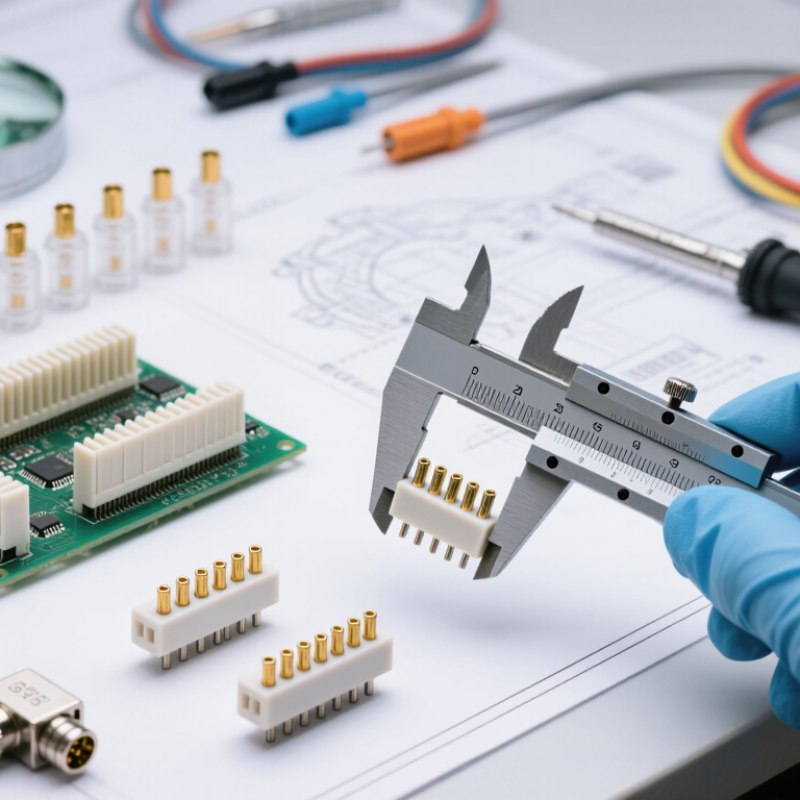
Table of Contents [Hide]
Define the 2510 Connector and Its Common Applications
How to Choose the Right 2510 Connector?
Define the 2510 Connector and Its Common Applications
A 2510 connector usually refers to a 2.54 mm pitch wire-to-board connector. Its name comes from the common housing designation, not a universal technical standard. Most versions use a plastic housing, metal crimp terminals, and matching PCB headers. Pin counts vary widely. Orientation may be vertical or right-angle.
These connectors carry low-voltage power and control signals in compact equipment. Typical applications include LED modules, sensors, small control panels, appliances, and embedded circuit boards. They suit prototypes and production assemblies when space and wiring access are limited. Some designs use friction locks. Others rely on a stronger latching structure.
Choosing one requires more than checking pin spacing. Confirm the rated current, voltage, wire size, contact material, and operating temperature. Check whether the terminal accepts solid or stranded wire. Mating direction also matters during installation. A right-angle version can prevent sharp wire bends inside a narrow enclosure.
Inspect the crimp after assembly. It should grip the conductor without cutting the strands. I have seen connectors fit physically but fail under vibration because the terminal was poorly crimped. That detail is easy to underestimate. Review the manufacturer’s drawings and test samples before approval. A connector that looks identical may have different tolerances, plating, or retention strength. Do not assume compatibility from appearance alone.
Brands
Proudly Trusted by Top Suppliers Worldwide







Let us know and we will automate, together to fit your industrial needs.
 +91-97254 16844
Clients
Proudly Trusted by Top Companies Worldwide


Do you need Help? Get in touch.
X
Please fill out the form below and we will get back to you as soon as possible.