o
p
t
i
m
a
r
o
b
o
t
i
c
s

Make a Call


Make a Call
Blogs
How to Choose the Right 3 Phase Socket?
Choosing the right 3 Phase Socket is more than matching voltage and plug shape. It affects equipment safety, uptime, energy distribution, and maintenance costs. In workshops, factories, commercial kitchens, and charging areas, one incorrect specification can create heat, nuisance tripping, or an unreliable connection.
Demand for dependable electrical infrastructure is increasing. The International Energy Agency’s Electricity 2024 report expects global electricity demand to grow strongly through 2026, supported by industry, data centers, cooling, and electrification. That growth makes correct connection design increasingly important. IEC 60309 standards provide internationally recognized requirements for industrial plugs, socket-outlets, and connectors, including rated current, voltage, polarity, and protection against environmental conditions.
A practical selection begins with the load. Check the motor or machine nameplate, not only the supply label. A 16 A socket may suit a light-duty tool, while a 63 A model may be required for heavy machinery. Voltage, frequency, number of poles, phase sequence, and earthing arrangement must also match. They are not interchangeable details. The enclosure rating matters too. A dusty workshop may need IP44 protection, while exposed washdown areas can require a higher rating.
Small details matter.
Consider cable size, installation method, ambient temperature, and expected duty cycle. IEC 60309 color coding can help identify voltage ranges, but color alone should never determine compatibility. Local electrical codes and qualified inspection remain essential. A limitation in this guide is simple: equipment conditions vary, and a socket that works well in one facility may be unsuitable elsewhere. Careful verification beats assumption.
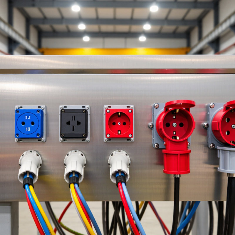
Table of Contents [Hide]
Understanding Three-Phase Socket Types and Their Applications
How to Choose the Right 3 Phase Socket?
Understanding Three-Phase Socket Types and Their Applications
A three-phase socket must match the supply system, equipment, and working environment. Common configurations include three poles plus earth, or three poles, neutral, and earth. Equipment without a neutral conductor may use the first type. Machines needing control circuits or single-phase accessories often require the second. Check the equipment plate before choosing. Guessing can damage machinery or create a serious shock risk.
Current rating matters as much as voltage. A small workshop motor may need a socket rated for 16 or 32 amps, while larger heating or pumping equipment requires more capacity. The socket’s pin arrangement and clock position must also match the plug. They prevent accidental connection between incompatible circuits. For outdoor areas, select suitable ingress protection against dust and water. Wet locations need extra care.
Application affects the design. Workshops commonly use wall-mounted sockets for motors, compressors, and welding equipment. Construction areas may need robust, impact-resistant versions with covers. Food-processing spaces often require smooth, easy-clean surfaces. An interlocked socket can prevent connection or disconnection while energized. That detail is easy to overlook.
A qualified electrician should verify phase sequence, earthing, cable size, and protective devices. Phase rotation can affect motor direction. It is a small check with a large consequence. Installation practice is not always perfect, and older systems may hide undocumented changes. Measure the actual supply instead of trusting labels alone.
Brands
Proudly Trusted by Top Suppliers Worldwide







Let us know and we will automate, together to fit your industrial needs.
 +91-97254 16844
Clients
Proudly Trusted by Top Companies Worldwide


Do you need Help? Get in touch.
X
Please fill out the form below and we will get back to you as soon as possible.