o
p
t
i
m
a
r
o
b
o
t
i
c
s

Make a Call


Make a Call
Blogs
7 Plastic Blind Drain Buying Tips for Global Buyers
A Plastic blind drain may look like a simple strip of molded material, but its performance depends on details buyers cannot judge from a product photo. Wall thickness, channel shape, filter fabric, and connection design can affect handling and drainage on site. Small details matter. A sample beside a project drawing often reveals more than a polished catalog image.
This guide presents seven practical buying tips for global buyers, from checking dimensions and material specifications to reviewing flow data, installation needs, packaging, and supplier quality records. Ask how test results were produced, and make sure they match the intended application. A drain suited to a landscaped walkway may not be suitable for a retaining wall or a heavily loaded area. It is easy to miss. Buyers should also confirm whether accessories and filter layers are included, rather than assuming the quoted product covers everything.
Experience helps, but it does not remove uncertainty. Product names can sound similar while designs differ, and a low unit price may not reflect freight, handling, or installation costs. Compare like with like, using written specifications and clear acceptance criteria. Still, no checklist can replace project-specific engineering review. That point is sometimes inconvenient, but important. Use these tips to ask better questions, reduce avoidable surprises, and choose a Plastic blind drain that fits the actual site conditions.
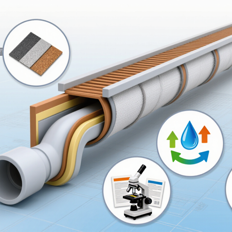
Table of Contents [Hide]
What a Plastic Blind Drain Is and Where It Is Used
A plastic blind drain is a prefabricated drainage element that collects and carries water through a shaped plastic core. Many designs wrap the core in filter fabric, which helps limit soil particles entering its channels. The exact structure varies, so the term is not perfectly consistent across suppliers. Buyers should check a product cross-section, not rely on its name alone.
These drains are used behind retaining walls, beside foundations, beneath landscaped areas, and in some road or sports-field drainage systems. For example, a strip may sit vertically against a basement wall, directing seepage toward a collector pipe. In a planted area, it may lie beneath the soil to reduce waterlogging. Water needs an exit. Without a suitable outlet and a continuous route, the drain may collect water without removing it.
Project conditions matter. Fine soil can clog an unsuitable filter, while heavy loads may require a stronger core. Check the fabric, flow capacity, compressive strength, dimensions, and installation details against the site design. A common gap in specifications is the outlet connection; it deserves a clear drawing. Drainage layouts can look simple on paper, but soil conditions and installation tolerances are not always simple in the field.
Brands
Proudly Trusted by Top Suppliers Worldwide







Let us know and we will automate, together to fit your industrial needs.
 +91-97254 16844
Clients
Proudly Trusted by Top Companies Worldwide


Do you need Help? Get in touch.
X
Please fill out the form below and we will get back to you as soon as possible.