o p t i m a r o b o t i c s

Blogs

What Are Sheet Metal Parts and How Are They Made?

Sheet Metal Parts are components formed from thin metal stock through controlled cutting, bending, and shaping. They appear in server enclosures, vehicle brackets, HVAC panels, kitchen equipment, and medical housings. Their simple appearance can hide demanding engineering decisions. Material thickness, alloy, grain direction, and bend radius affect strength and fit. A reliable design begins with the part’s function, not merely its outline.

Manufacturers commonly use laser cutting, punching, shearing, press-brake forming, stamping, and sometimes welding. Each method suits different volumes, geometries, and tolerance requirements. For example, a laser can produce clean profiles, while a press brake creates accurate folds along planned bend lines. Experienced fabricators also account for springback, tool clearance, edge distortion, and burr formation. Small details matter.

Quality depends on more than modern machinery. Engineers review drawings, select suitable metals, and verify dimensions with calipers, gauges, or coordinate measuring equipment. Surface finish and corrosion protection may also require deburring, powder coating, plating, or passivation. Yet no process is flawless. Unexpected warping can appear after forming, and a design that works on paper may resist efficient production. Careful prototyping, documented inspections, and honest feedback reduce these risks. This guide explains how Sheet Metal Parts are designed, made, and evaluated, while recognizing that practical judgment remains essential.
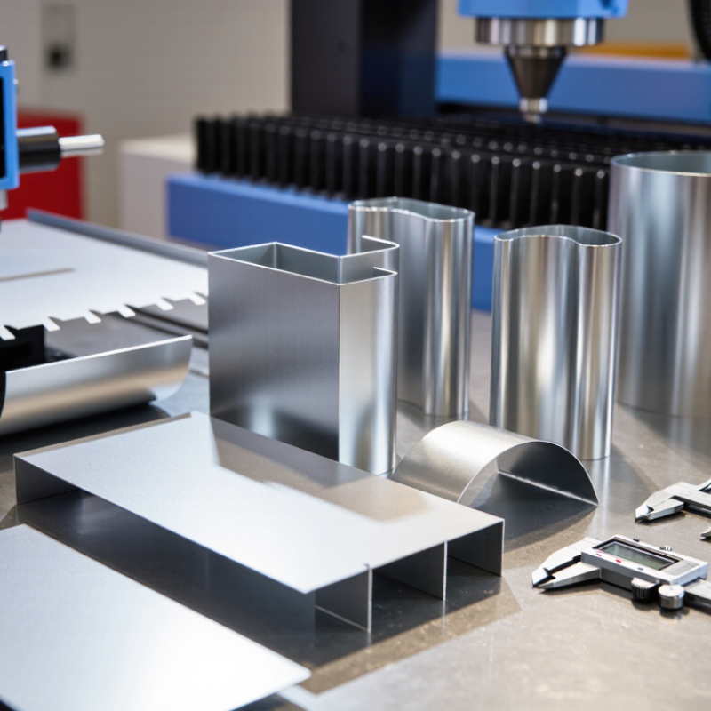
What Are Sheet Metal Parts and How Are They Made?

What Are Sheet Metal Parts?

Sheet metal parts are components formed from thin, flat metal sheets. They can become brackets, panels, enclosures, frames, ducts, and protective covers. Common materials include steel, stainless steel, aluminum, and copper. Each material behaves differently during cutting and forming.

A fabricator may cut a sheet with a laser, punch, or shear. Bending machines then create precise angles, flanges, or channels. Some parts require welding, riveting, threading, or surface finishing. A small enclosure, for example, may start as a 1.5-millimeter aluminum sheet. After cutting and bending, it can protect electrical equipment from dust and physical contact.

Good sheet metal parts depend on more than a clean drawing. Designers must consider material thickness, bend radius, grain direction, hole spacing, and tool access. Tight bends can cause cracking. Tiny holes may distort during forming. A practical design leaves enough space around each feature. It also allows inspection with calipers, gauges, or a simple test assembly.

Manufacturing tolerances matter. They affect fit, strength, appearance, and assembly speed. Powder coating or plating may improve corrosion resistance, but finishing adds thickness. That change can affect tight joints. No design is perfect. A part that looks efficient on screen may waste material or require difficult setup. Careful review and prototype testing often reveal those hidden problems.

Which Metals Are Used in Sheet Metal Parts?

Sheet metal parts are shaped from flat metal sheets through cutting, bending, punching, stamping, or rolling. The selected metal affects strength, weight, corrosion resistance, appearance, and production cost. In practical fabrication, material choice often determines whether a part performs reliably after repeated use.

Carbon steel is widely used for brackets, enclosures, frames, and industrial panels. It offers high strength and straightforward forming, but it usually needs paint, plating, or another protective finish. Stainless steel resists moisture, chemicals, and staining. It suits food-processing equipment, medical structures, and outdoor components, although it costs more and requires careful welding control. Aluminum is lightweight and naturally corrosion resistant. It works well for covers, vehicle panels, and parts that need easier handling. However, its lower stiffness can cause unwanted flexing. Copper conducts heat and electricity efficiently, while brass provides useful corrosion resistance and an attractive surface. These metals are often chosen for electrical parts, fittings, and decorative hardware. A choice may look perfect on paper, then fail during forming or assembly. That happens more often than many design teams admit.

Tips: Match the metal to its working environment, not appearance alone. Check thickness, bend radius, temper, and finishing requirements before cutting. Galvanized steel protects well, but its coating can complicate welding and finishing. Small prototypes reveal problems early. They also expose assumptions that drawings may hide.

What Are Sheet Metal Parts and How Are They Made? - Which Metals Are Used in Sheet Metal Parts?

Typical values are approximate and may vary according to alloy, temper, thickness, surface condition, and manufacturing standards.
Material or Process Typical Grades or Forms Key Physical Data Main Characteristics Common Sheet-Metal Applications
Common Metals Used in Sheet Metal Parts
Low-carbon steel Mild steel; commercial-quality or drawing-quality sheet Density: approximately 7.85 g/cm³
Melting range: approximately 1,370–1,530°C
High stiffness, good formability, easy welding, and relatively low material cost. Requires coating or painting for long-term corrosion protection. Brackets, cabinets, enclosures, automotive panels, structural covers, and general fabrication.
Galvanized steel Zinc-coated carbon-steel sheet Steel density: approximately 7.85 g/cm³
Common zinc coating: approximately 60–275 g/m² total, depending on specification
Provides sacrificial corrosion protection through a zinc coating. Suitable for bending, but excessive forming can damage the coating. Ductwork, roofing components, electrical boxes, appliance panels, and outdoor enclosures.
Stainless steel Austenitic grades such as 304 and 316; ferritic grades such as 430 Density: approximately 7.7–8.0 g/cm³
Melting range: approximately 1,370–1,510°C
Strong corrosion resistance due to chromium content. Austenitic grades generally have excellent ductility; work hardening can increase forming force. Food-processing equipment, medical components, kitchen panels, chemical equipment, railings, and decorative parts.
Aluminum 5052, 6061, 3003, and similar sheet alloys Density: approximately 2.70 g/cm³
Melting range: approximately 570–655°C, depending on alloy
About one-third the density of steel, naturally corrosion resistant through an oxide layer, and easy to machine. Some alloys have limited formability or weldability in hardened tempers. Lightweight housings, transportation panels, heat shields, electronics enclosures, signage, and ventilation parts.
Copper Commercially pure copper and oxygen-free copper sheet Density: approximately 8.96 g/cm³
Melting point: approximately 1,085°C
Very high electrical and thermal conductivity, excellent ductility, and good atmospheric corrosion resistance. It is relatively heavy and can be prone to surface scratching. Electrical busbars, grounding components, heat exchangers, roofing details, and decorative panels.
Brass Copper-zinc sheet alloys, including cartridge brass and free-machining brass Density: approximately 8.4–8.7 g/cm³
Melting range: approximately 900–950°C, depending on composition
Good machinability, attractive appearance, moderate corrosion resistance, and useful electrical conductivity. Formability varies with zinc content and temper. Decorative panels, electrical terminals, instrument parts, fittings, nameplates, and architectural details.
Titanium Commercially pure titanium and alpha-beta titanium sheet Density: approximately 4.51 g/cm³
Melting point: approximately 1,668°C
High strength-to-weight ratio and excellent corrosion resistance. More difficult to form, cut, and weld than common steel or aluminum. Aerospace parts, chemical-processing equipment, marine components, and high-performance enclosures.
Typical Sheet-Metal Manufacturing Stages
1. Material selection and design Sheet, coil, or plate selected by alloy, thickness, temper, and surface finish Common thickness range: approximately 0.5–6 mm for many fabricated parts The design must account for bend radius, bend allowance, springback, grain direction, tolerances, and material behavior. Flat patterns, engineering drawings, 3D models, and production specifications.
2. Cutting Laser cutting, punching, shearing, waterjet cutting, or plasma cutting Process choice depends on thickness, geometry, heat sensitivity, edge quality, and production volume. Creates the blank or flat pattern. Secondary deburring may be required to remove sharp edges and burrs. Profiles, holes, slots, vents, tabs, and mounting features.
3. Forming and bending Press-brake bending, roll forming, stamping, deep drawing, or hemming Bend radius is normally specified relative to material thickness and alloy formability. Changes the shape without removing substantial material. Springback compensation may be needed, especially with high-strength alloys. Channels, brackets, trays, covers, shells, frames, and three-dimensional housings.
4. Joining Welding, riveting, clinching, bolting, or adhesive bonding Selection depends on joint strength, appearance, heat input, dissimilar metals, and service environment. Joins individual parts into an assembly. Heat-affected zones and distortion must be controlled during welding. Frames, cabinets, equipment housings, structural assemblies, and sealed enclosures.
5. Finishing and inspection Deburring, grinding, polishing, powder coating, painting, anodizing, plating, or passivation Inspection may include dimensional checks, visual inspection, coating thickness, flatness, and joint quality. Improves appearance, corrosion resistance, wear resistance, electrical properties, and user safety. Finished panels, visible housings, sanitary components, outdoor parts, and precision assemblies.

How Is Sheet Metal Prepared for Manufacturing?

Preparing sheet metal starts before cutting. I verify the material certificate, alloy, thickness, temper, surface, and heat number. A micrometer checks thickness at several points, not one convenient edge. Flatness matters, especially for large laser-cut blanks. A perfect flatness assumption is tempting, but usually wrong.

The World Steel Association recorded 1,892.1 million tonnes of crude steel production in 2023 (World Steel in Figures 2024). That scale makes traceability more than paperwork. It protects the correct grade from being mixed during storage.

USGS Mineral Commodity Summaries 2024 estimated 2.5 billion tonnes of global iron ore mine production in 2023. Material selection still carries a resource cost.

Before nesting, CAD files need bend lines, hole sizes, grain direction, and finished tolerances. Designers should confirm minimum bend radius against grade and thickness. The press-brake setup uses bend allowance or K-factor, not guesswork.

Grain direction can change springback and edge quality. Nesting software reduces skeleton waste, although the highest yield is not always safest. Tiny bridges may distort during cutting.

I prefer test coupons when tolerances are tight. They reveal burrs, heat-affected edges, and actual bend behavior. Cutting parameters are then adjusted for assist gas, power, and speed.

Deburr and clean before forming if contamination can mark the surface. Parts receive identification and inspection records.

One weak point remains: drawings may hide assumptions. A short manufacturing review often catches them.

What Are the Main Steps in Sheet Metal Fabrication?

What Are Sheet Metal Parts and How Are They Made?

Sheet metal parts are components formed from thin metal sheets. They appear in enclosures, brackets, panels, ducts, and machine covers. The fabrication process begins with a precise digital drawing. Engineers define dimensions, hole locations, bend angles, and allowable tolerances. Material selection follows the part’s purpose. Steel offers strength, while aluminum reduces weight and resists corrosion. Thickness also affects cutting and bending results.

The sheet is cut into a flat pattern using laser cutting, shearing, or punching equipment. Operators remove sharp burrs from the cut edges. Bending then creates the required three-dimensional shape. A press brake applies controlled force along marked bend lines. Each bend needs a suitable tool, angle, and allowance for material springback. Small errors can change the final fit. Joining may involve welding, riveting, or mechanical fastening. Surface treatment can improve appearance and protect against moisture. Final inspection checks dimensions, hole alignment, surface quality, and joint strength. In practical fabrication, perfect results rarely come from cutting alone. Careful inspection matters.

Tips: Keep drawings clear and review bend directions before production. Use samples to verify critical dimensions. Do not ignore burrs, even when they seem minor. They can affect assembly and create safety concerns. Record inspection results for reliable quality control. Recheck unusual designs; assumptions sometimes fail.

What Are the Main Steps in Sheet Metal Fabrication?

Sheet metal fabrication typically follows a six-stage workflow: design, material selection, cutting, forming, joining, and finishing and inspection. The sequence may vary depending on the part geometry, material, tolerance, and production volume.

Where Are Sheet Metal Parts Used?

Sheet metal parts appear in more places than many people realize. In buildings, they form air ducts, roofing panels, wall cladding, and protective covers. Their thin, shaped surfaces move air, block moisture, and protect hidden systems. In factories, sheet metal becomes machine guards, electrical enclosures, control cabinets, and equipment frames. These parts must often balance strength, weight, access, and appearance.

Transportation uses sheet metal for brackets, body panels, battery covers, and interior supports. Household products also depend on it. Washing machines, ovens, shelving units, and lighting housings commonly use folded steel or aluminum.

Medical and laboratory equipment may require smooth surfaces, accurate bends, and easy cleaning. Manufacturers usually cut flat sheets with lasers, punches, or shears, then bend them with press brakes. Welding, riveting, or mechanical fastening joins the finished pieces.

Tips: Select the material according to corrosion, heat, and load requirements. Leave enough bend space near holes and edges. Sharp corners can increase injury risks and fabrication costs. A simple prototype often reveals problems that drawings miss.

In practical fabrication, small details matter. A misplaced hole can interfere with a fastener or block maintenance access. Thin material may look efficient, yet it can vibrate or dent during use. Designers sometimes focus too heavily on appearance. That choice may create weak corners, difficult repairs, or unnecessary waste. Better results come from reviewing the part’s real environment before production.

Brands

Proudly Trusted by Top Suppliers Worldwide

Let us know and we will automate, together to fit your industrial needs.

Clients

Proudly Trusted by Top Companies Worldwide

Do you need Help? Get in touch.

X

Please fill out the form below and we will get back to you as soon as possible.

    Subscribe our newsletter & get updates







