o
p
t
i
m
a
r
o
b
o
t
i
c
s

Make a Call


Make a Call
Blogs
7 Tips for Buying a JS1500 Concrete Mixer?
Buying a Js1500 Concrete Mixer is not simply a capacity decision. It is a production decision.
A JS1500 mixer can deliver about 1.5 cubic metres per batch, but output depends on more than its rated volume. Mixing time, aggregate moisture, cement quality, and operator experience all affect results. A machine may look powerful on a showroom floor. Its true value appears beside a dusty batching plant, where every batch must remain stable.
Concrete equipment consultant Colin L. Lobo offers a useful principle: “Consistent concrete begins with controlled materials and a properly maintained mixer.” That idea should guide every inspection. Buyers should check the twin-shaft mixing arms, discharge gate, liners, bearings, hydraulic system, and control cabinet. Small wear marks can signal larger maintenance costs later. Ask for service records, spare-parts availability, and realistic delivery support.
The seven tips in this guide focus on practical buying choices. They cover capacity, motor performance, mixing uniformity, build quality, automation, maintenance, and supplier reliability. A Js1500 Concrete Mixer should match your aggregate size, concrete recipes, daily output, and site conditions. It should not be selected because its specification sheet looks impressive.
There is also room for doubt. Some buyers focus too heavily on price. That can be a mistake. Others assume every JS1500 model performs identically. They do not. Compare test batches when possible. Listen for abnormal gearbox noise. Inspect the mixer after operation, not only before it. A careful decision today can reduce downtime, rejected concrete, and unpleasant surprises tomorrow.
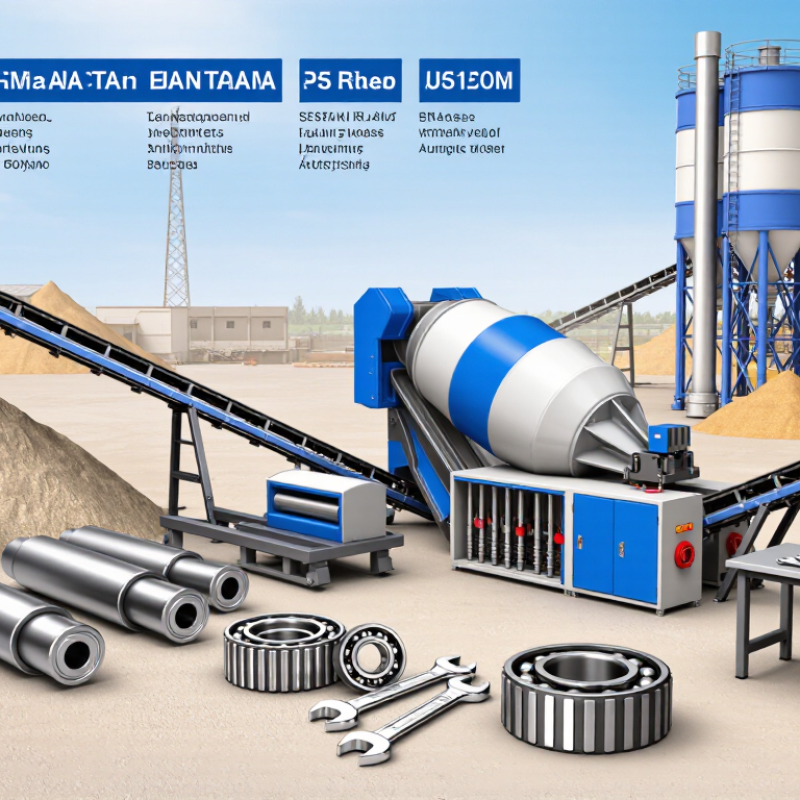
Table of Contents [Hide]
Define the JS1500 Concrete Mixer and Its Main Applications
7 Tips for Buying a JS1500 Concrete Mixer
Define the JS1500 Concrete Mixer and Its Main Applications
A JS1500 concrete mixer is a twin-shaft forced mixer designed for intensive concrete production. Its 1500-liter nominal discharge capacity suits medium and large batching operations. Unlike a simple drum mixer, it uses synchronized horizontal shafts and mixing arms. These components spread cement, aggregates, water, and admixtures through a strong shearing action. The result is usually a more uniform mixture in less time.
It is commonly used in ready-mix plants, precast yards, road projects, bridge construction, and water infrastructure. It can handle ordinary concrete, dry concrete, and many higher-strength formulations. On an active site, operators often value its fast discharge and consistent mixing cycle. However, output is not determined by capacity alone. Aggregate moisture, loading sequence, material size, and cleaning habits affect real production. That detail is easy to overlook.
Before buying, inspect the shaft seals, mixing arms, liners, discharge gate, and maintenance access. Ask for verified cycle data under materials similar to yours. A supplier’s maximum figure may assume ideal conditions. It may not match your daily workload. Check motor power, spare-part availability, safety interlocks, and local technical support. A well-built mixer still performs poorly when worn liners remain unnoticed. Regular inspection matters. Also, leave enough space around the machine for safe cleaning and repairs.
Brands
Proudly Trusted by Top Suppliers Worldwide







Let us know and we will automate, together to fit your industrial needs.
 +91-97254 16844
Clients
Proudly Trusted by Top Companies Worldwide


Do you need Help? Get in touch.
X
Please fill out the form below and we will get back to you as soon as possible.