o
p
t
i
m
a
r
o
b
o
t
i
c
s

Make a Call


Make a Call
Blogs
What Is a TL130 Bottom Roller and How Does It Work?
A Tl130 Bottom Roller is a load-bearing undercarriage component, not simply a steel wheel beneath a crawler machine. It supports track-chain movement, guides alignment, and absorbs repeated impact across soil, gravel, and uneven work sites. Its condition influences tracking accuracy, vibration, fuel use, and final-drive stress. Small seal damage can become expensive quickly.
The global construction equipment market continues to expand, while equipment owners face stronger pressure to reduce downtime. Grand View Research has projected a construction equipment market compound annual growth rate of about 5.8% from 2023 to 2030. McKinsey & Company has also reported that predictive maintenance can reduce machine downtime by roughly 30% to 50%. These figures do not describe the Tl130 Bottom Roller specifically. They do show why component inspection deserves careful attention.
Quality expert W. Edwards Deming offered a useful warning: “Without data, you’re just another person with an opinion.” For a Tl130 Bottom Roller, data means checking roller diameter, flange wear, oil leakage, bearing noise, track sag, and operating hours. Measure it. Do not guess.
A practical inspection may reveal polished metal on one flange, a damp seal, or uneven wear across the roller surface. Those details can indicate misalignment, incorrect tension, poor lubrication, or a worn track chain. However, one limitation deserves honesty: replacement dimensions and fitment can vary by machine configuration. Part numbers alone may mislead. Verify the manufacturer’s specifications, serial number, mounting width, shaft size, and seal design before purchasing. This guide explains how the roller works, how it fails, and where routine maintenance can prevent an avoidable repair.
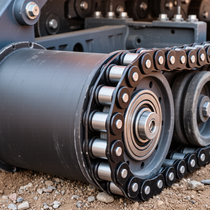
Table of Contents [Hide]
TL130 Bottom Roller: Definition, Function, and 130-Class Undercarriage Data
A TL130 bottom roller is a lower track roller used in a TL130 or similar 130-class undercarriage. It supports the machine’s weight between the track chain and frame. Its steel body rotates around sealed bearings while the track chain passes over it. This reduces sliding resistance and helps the track move in a controlled path. The roller is small compared with the machine, but its job is not minor.
For 130-class undercarriages, practical reference data often includes an operating weight of about 12 to 16 tonnes, track shoes around 600 to 700 millimeters wide, and roughly 7 to 9 bottom rollers on each side. Exact figures vary by configuration, working attachment, shoe pattern, and frame design. A TL130 bottom roller must match the correct shaft length, flange profile, mounting pattern, and seal arrangement. A small mismatch can cause poor alignment or accelerated chain wear.
From field inspections, uneven roller wear is often visible before serious damage occurs. One roller may show a polished edge, oil leakage, or a rough turning sound. That detail matters. However, visual inspection alone is imperfect. Mud can hide cracks, and a quiet roller may still have damaged bearings. I prefer checking roller rotation, side play, oil condition, and track tension together. The service manual remains the reliable reference, especially when 130-class data appears similar across different machines.
Brands
Proudly Trusted by Top Suppliers Worldwide





Let us know and we will automate, together to fit your industrial needs.
 +91-97254 16844
Clients
Proudly Trusted by Top Companies Worldwide


Do you need Help? Get in touch.
X
Please fill out the form below and we will get back to you as soon as possible.