o
p
t
i
m
a
r
o
b
o
t
i
c
s

Make a Call


Make a Call
Blogs
China Top SPDT Micro Switch Manufacturers and Suppliers
Choosing the right spdt micro switch supplier requires more than comparing prices or browsing attractive product pages. Performance depends on contact materials, actuator design, terminal construction, and production consistency. A switch may look identical to another model, yet behave differently under vibration, dust, or repeated operation. Small details matter.
China has a broad manufacturing base for micro switches, serving appliances, industrial controls, automotive systems, and electronic equipment. Experienced manufacturers may offer custom levers, varied actuation forces, sealed housings, and flexible terminal options. However, supplier quality is not uniform. Buyers should examine factory experience, engineering support, inspection procedures, sample performance, and documented quality systems. Certifications can support confidence, but they should be verified against the exact product and production site. Paperwork alone is not enough.
This guide introduces leading Chinese manufacturers and suppliers of spdt micro switch products. It focuses on practical selection points, including switching ratings, mechanical life, electrical life, operating temperature, tolerances, and delivery capability. Clear drawings and realistic testing conditions can prevent costly misunderstandings. Ask for samples. Test them.
The evaluation also recognizes an uncomfortable point: published specifications do not always predict field performance. A switch tested in a clean laboratory may face moisture, dust, impact, or uneven installation in real equipment. For that reason, buyers should combine supplier documentation with application testing and direct technical communication. No ranking is permanently perfect. Manufacturing conditions, materials, and service quality can change over time. Careful verification remains essential.
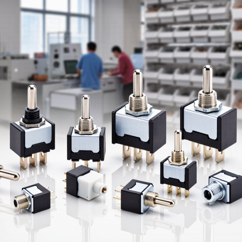
Table of Contents [Hide]
What Is a SPDT Micro Switch and How Does It Work?
A SPDT micro switch is a compact electromechanical device with one common terminal and two selectable outputs. SPDT means Single Pole, Double Throw. The common terminal connects to either the normally closed or normally open contact.
At rest, the common terminal usually touches the normally closed contact. Pressing the actuator moves an internal spring mechanism and changes the electrical path. Releasing it returns the contact, provided the switch is designed for momentary operation. This tiny movement can control a motor, safety interlock, control panel, or position sensor. The click is useful feedback, but it is not proof of reliable switching.
A 2024 Grand View Research assessment estimates the global microswitch market at approximately USD 1.3 billion in 2023, with continued growth forecast through 2030. Market figures differ between reports because product definitions vary. That limitation deserves attention. Engineers should not use market growth as a substitute for component testing.
IEC 61058-1 provides important guidance for switch safety and performance. In practice, selection depends on current rating, voltage, actuator force, travel, contact resistance, and mechanical life. Contact bounce can create false signals in digital circuits, so firmware filtering or a hardware debounce circuit may be necessary. A supplier should provide test conditions, not only attractive cycle numbers. The real question is simple: will the switch perform consistently after dust, vibration, repeated pressing, and small installation errors?
Brands
Proudly Trusted by Top Suppliers Worldwide







Let us know and we will automate, together to fit your industrial needs.
 +91-97254 16844
Clients
Proudly Trusted by Top Companies Worldwide


Do you need Help? Get in touch.
X
Please fill out the form below and we will get back to you as soon as possible.