o
p
t
i
m
a
r
o
b
o
t
i
c
s

Make a Call


Make a Call
Blogs
What Is TVS Surge Protection and How Does It Work?
Modern electronics rarely fail because of normal operating voltage alone. A brief surge from an inductive load, cable discharge, or nearby lightning event can create a sharp electrical spike. Tvs Surge Protection helps limit that spike before it damages sensitive components. TVS means transient voltage suppressor. A TVS diode normally remains nearly inactive. When voltage exceeds its designed threshold, it conducts excess current away from the protected circuit. This action reduces the voltage reaching processors, communication ports, sensors, and power inputs.
The process looks simple, but correct selection requires careful engineering. Designers compare stand-off voltage, breakdown voltage, clamping voltage, peak pulse current, and capacitance. A part that clamps effectively may still interfere with a high-speed data line. A small diode may protect a signal but fail under a powerful surge. Datasheet graphs matter more than attractive product claims. Testing should also consider the real wiring layout, grounding path, and expected surge waveform. IEC 61000-4-5 testing can provide useful guidance, although laboratory results do not perfectly represent every installation.
No protector is magic. Tvs Surge Protection can reduce surge energy, not eliminate every electrical risk. I have found that many explanations overlook heat, repeated events, and poor PCB routing. That omission deserves reflection. A short connection to the return path often matters as much as the selected component. Reliable protection combines a suitable TVS diode, sound circuit design, verified testing, and maintenance based on actual operating conditions. The following sections explain how the device responds, where it belongs, and which specifications deserve the closest attention.
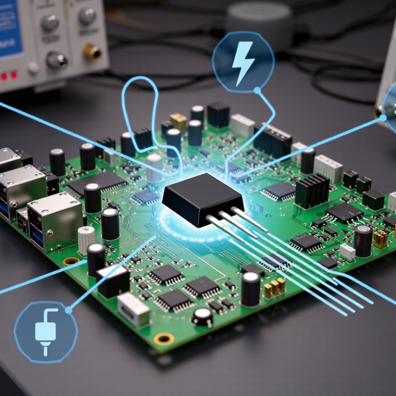
Table of Contents [Hide]
What Is TVS Surge Protection?
TVS surge protection uses a transient-voltage-suppression diode to limit sudden electrical spikes. Under normal voltage, the diode remains nearly inactive. When a transient exceeds its breakdown threshold, it conducts excess current toward ground or another safe return path. The voltage across the protected circuit then stays near the specified clamping level. Fast action matters. A TVS diode can respond within nanoseconds, helping protect USB ports, sensor inputs, power rails, and communication lines. IEC 61643-11 provides testing principles for surge protective devices, but a compliant test does not guarantee perfect field performance.
Selection requires more than matching a voltage number. Engineers compare working standoff voltage, breakdown voltage, clamping voltage, peak pulse current, and pulse energy. For a 5 V signal line, excessive capacitance can distort data edges. A low-capacitance device may be safer electrically, but it can tolerate less energy. Placement is equally important. Short traces, a solid ground path, and minimal loop area reduce unwanted inductance. In real testing, a long ground wire can make a good protector appear ineffective. It is easy to miss this detail.
The 2024 Annual Outage Analysis from Uptime Institute reported that 54% of surveyed outages cost more than 100,000 dollars. This figure does not prove surges caused those events. It does show why transient control deserves practical attention. TVS protection is not a cure-all. A poorly chosen diode can fail early, clamp too late, or interfere with normal signals. Oscilloscope testing under realistic cable and load conditions remains necessary.
Brands
Proudly Trusted by Top Suppliers Worldwide







Let us know and we will automate, together to fit your industrial needs.
 +91-97254 16844
Clients
Proudly Trusted by Top Companies Worldwide


Do you need Help? Get in touch.
X
Please fill out the form below and we will get back to you as soon as possible.