o
p
t
i
m
a
r
o
b
o
t
i
c
s

Make a Call


Make a Call
Blogs
What Is a Transformer Core Cutting Line?
A Transformer Core Cutting Line is an integrated production system for converting electrical steel coils into precise laminations. These laminations form the magnetic core inside distribution and power transformers. The line usually combines decoiling, feeding, measuring, cutting, stacking, and scrap collection equipment. Its purpose is not simply to cut metal. It must protect magnetic performance while maintaining stable dimensions.
In practical production, grain-oriented electrical steel passes through guided rollers before high-speed blades create mitred or step-lap joints. A small cutting error can increase assembly gaps, noise, and no-load losses. Operators therefore monitor blade condition, strip tension, burr height, stacking alignment, and insulation coating damage. Experienced technicians also compare actual measurements with drawings and approved process limits. Modern equipment may include servo drives, automatic length control, laser positioning, and data recording. These features improve repeatability, but they do not remove the need for human judgment.
No line is perfect. Material variation, worn tooling, or poor calibration can still affect results. That is easy to underestimate. A reliable manufacturer validates cutting accuracy through routine inspections, trial runs, and documented maintenance. Engineers should also consider transformer size, steel grade, joint design, production volume, and factory space before selecting equipment. Safety guarding and controlled access remain essential around moving coils and cutting tools. This guide explains how a Transformer Core Cutting Line works, which components influence quality, and why careful process control matters. Some details vary between suppliers, so technical claims should be checked against equipment specifications, standards, and verified production records.
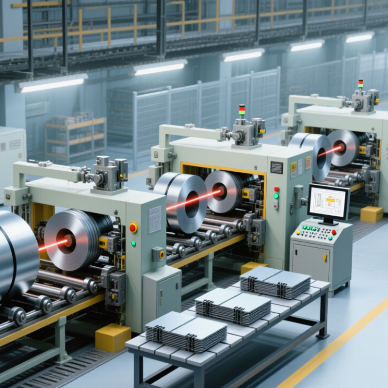
Table of Contents [Hide]
Definition and Purpose of a Transformer Core Cutting Line
A transformer core cutting line is an integrated production system for preparing electrical steel sheets. It cuts, trims, and stacks thin strips into accurate core sections. These sections guide magnetic flux inside a transformer. The main purpose is to reduce energy loss, improve core assembly, and support stable transformer performance. By controlling strip length, angle, and alignment, the line creates repeatable shapes for different core designs. In practice, even a small cutting error can affect the final assembly.
A typical line includes a decoiler, feeding unit, precision shear, scrap collection system, and stacking equipment. Sensors monitor position and movement during operation. Accurate cutting reduces burrs and limits unwanted gaps between steel pieces. This matters. Gaps can increase noise, vibration, and magnetic losses. Experienced technicians still need to check blade condition, material tension, and stacking quality. No machine removes every risk. Settings may work well today but require adjustment tomorrow.
Tips: Inspect cut edges under good lighting before production continues. Keep the feeding path clean and free from loose steel fragments. Record key settings for each material thickness. Do not judge quality by speed alone. A clean edge helps. Small errors accumulate. Reviewing actual results remains essential, because production conditions are rarely perfect.
Brands
Proudly Trusted by Top Suppliers Worldwide





Let us know and we will automate, together to fit your industrial needs.
 +91-97254 16844
Clients
Proudly Trusted by Top Companies Worldwide


Do you need Help? Get in touch.
X
Please fill out the form below and we will get back to you as soon as possible.