o
p
t
i
m
a
r
o
b
o
t
i
c
s

Make a Call


Make a Call
Blogs
Why Use Lifting Bolts for Heavy Loads?
Why Use Lifting Bolts for Heavy Loads?
Moving a heavy machine is not simply a matter of choosing the largest bolt available. Lifting Bolts provide engineered attachment points for cranes, hoists, spreader bars, and other controlled lifting equipment. Their threaded design allows secure installation into prepared holes, while their lifting eyes or shoulders guide force along a planned load path.
Dr. John A. Bickford, a respected bolting specialist and author of An Introduction to the Design and Behavior of Bolted Joints, stated, “A bolted connection is a carefully designed system, not merely a piece of hardware.” This principle applies directly to Lifting Bolts. Their performance depends on thread engagement, material strength, loading direction, surface condition, and correct installation.
Imagine a fabricated steel frame rising slowly from a workshop floor. The bolt may look simple, but every visible detail matters. A damaged thread, uneven seating surface, or angled pull can reduce safety margins. Manufacturers also specify working load limits, and those limits should never be treated as suggestions.
There is an uncomfortable point here. Many lifting failures begin with assumptions, not dramatic defects. Someone may reuse a worn bolt, ignore a side load, or trust appearance over inspection. That approach is risky.
Proper selection should include load calculation, compatibility checks, visual inspection, and a controlled lifting plan. Lifting Bolts can make heavy-load handling more predictable, but they cannot correct poor engineering. Used carefully, they support safer operations, repeatable positioning, and better protection for workers, equipment, and surrounding structures.
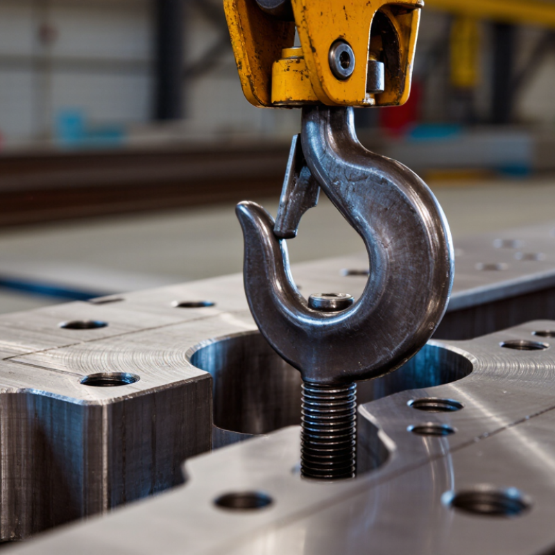
Table of Contents [Hide]
Load Paths: How Lifting Bolts Transfer Forces Under WLL Ratings
Why Use Lifting Bolts for Heavy Loads?
Lifting bolts create a defined load path between the suspended load and lifting equipment. Force travels through the bolt head, shank, threads, and base material. Under a rated WLL, the main force should remain axial and evenly distributed. Side loading changes that path quickly.
The danger is often at the connection, not the bolt itself. A tilted sling can introduce bending, while shallow thread engagement can cause pull-out. ASME B30.26 requires below-the-hook hardware to be marked and used within its rated limits. ISO 3266 also addresses lifting points and working load limits for general lifting applications. WLL is not breaking strength.
Load geometry matters. A vertical 2,000-kilogram load produces about 19.6 kilonewtons of gravitational force before dynamic effects. Two lifting bolts do not automatically share this force equally. Uneven sling angles, stiffness, and placement can overload one point. Small errors become expensive.
Safety data supports careful planning. The U.S. Bureau of Labor Statistics recorded 5,283 fatal work injuries in 2023. The U.K. Health and Safety Executive reported 138 worker fatalities during 2023/24. These figures are not lifting-bolt-specific, but they show why rated hardware needs disciplined inspection. Check thread condition, seating, alignment, and visible deformation. Then verify the actual load path, not just the stamped rating. Real installations are rarely perfect.
Brands
Proudly Trusted by Top Suppliers Worldwide






Let us know and we will automate, together to fit your industrial needs.
 +91-97254 16844
Clients
Proudly Trusted by Top Companies Worldwide


Do you need Help? Get in touch.
X
Please fill out the form below and we will get back to you as soon as possible.