o p t i m a r o b o t i c s

Blogs

How to Choose the Right Robot Vision System?

Choosing the right robot vision system starts with the task, not the camera. A glossy product image means little without measurable requirements. Define the object’s size, surface, speed, position tolerance, and failure cost. Then examine lighting, lens selection, field of view, processing time, and robot communication. A system that detects a metal part under controlled light may fail on oily plastic.

The International Federation of Robotics reported 541,302 industrial robots installed worldwide in 2023, in its World Robotics 2024 report. More robots increase the need for dependable perception. However, market growth does not guarantee a suitable solution. Performance depends on integration quality, operator training, maintenance, and usable production data. David Marr wrote in Vision, “The purpose of vision is to discover what is present in the world, and where it is.” That principle still matters. Robot vision must create decisions, not merely attractive images.

Look closely at the production scene. Does sunlight shift across the inspection area? Do reflective surfaces overwhelm the sensor? Can the system reject one defective part without stopping the entire line? Check accuracy at the real cycle time, not only in a laboratory demonstration. Test representative parts, including damaged, dirty, and unusual examples. A neat specification sheet can hide difficult edge cases. That is where this choice becomes less certain. Some applications need 2D cameras, while others justify 3D sensing, thermal imaging, or AI-based inspection. The right system is rarely the most advanced one. It is the system that delivers stable results, explains failures, and remains maintainable after installation.
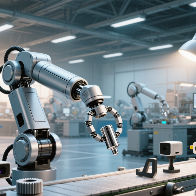
How to Choose the Right Robot Vision System?

Understanding the Role of Robot Vision in Automated Systems

Robot vision is the sensing layer that helps automated systems understand position, shape, distance, and change. The right system depends on the task, not the camera alone. A 2D camera may locate labels on a flat conveyor. A 3D system may better handle uneven parts, height differences, or random placement. Lighting matters just as much. Glare, dust, vibration, and changing shadows can weaken a strong algorithm.

The scale is significant. The International Federation of Robotics reported 541,302 industrial robots installed worldwide in 2023, with more than 4.2 million operating robots in factories.

As automation expands, vision must support faster decisions and safer handoffs. Choose a system by measuring cycle time, field of view, resolution, detection accuracy, and false-rejection rates. Test real parts, including scratched and poorly positioned samples. Clean samples are not enough.

A practical trial should connect the camera, software, robot controller, and production database. Check calibration drift after temperature changes. Check image latency during peak throughput. A neat specification sheet can still mislead. I have found that operators often notice failures before engineers do. Their feedback deserves structured testing, not casual discussion.

Industry research also reflects strong momentum: Grand View Research projects continued double-digit growth for the machine vision market through 2030. Yet market growth does not guarantee a suitable deployment. Selectable lighting, explainable inspection rules, maintainable components, and documented validation usually matter more than impressive image resolution. (Sources: IFR, World Robotics 2024; Grand View Research, Machine Vision Market Size Report, 2024.)

Defining Application Needs and Visual Inspection Goals

How to Choose the Right Robot Vision System?

Defining application needs should come before comparing cameras, lenses, or software. Start with the inspection goal: detect missing parts, measure dimensions, read codes, or guide a robot. Each goal requires different image quality, speed, and lighting control. A scratched surface may need controlled illumination, while precise measurement demands stable calibration. In practice, teams often describe defects vaguely. “Find bad parts” is not enough. Define acceptable limits, inspection speed, and false-rejection tolerance.

The International Federation of Robotics reported 541,302 industrial robots were installed worldwide in 2023. This growth increases pressure on vision systems to inspect quickly and consistently. However, more resolution does not always mean better performance. Excessive detail can slow processing and expose irrelevant texture. Test representative samples, including clean parts, borderline defects, dust, reflections, and natural position changes. Record results. Then compare detection accuracy, cycle time, and maintenance effort. A perfect specification rarely survives contact with production.

Tips: Write the inspection decision in one sentence. Measure the smallest defect that matters. Use real production lighting during trials. Check how operators will clean lenses and verify calibration. Keep a failure log, because early assumptions are often wrong. The Association for Advancing Automation notes that automation projects depend heavily on application fit and system integration, not hardware alone. Therefore, assess the camera, lighting, algorithms, robot movement, and factory environment as one working system.

How to Choose the Right Robot Vision System? - Defining Application Needs and Visual Inspection Goals

Inspection Goal Typical Application Need Recommended Vision Capability Important Image Factors Useful Output or Metric Key Selection Question
Presence and Absence Detection Confirm that a component, fastener, label, cap, connector, or package is present before the next process step. 2D area-scan imaging with suitable contrast, controlled lighting, and binary or pattern-based inspection tools. Object contrast, background variation, part orientation, camera distance, and cycle-to-cycle lighting stability. Pass/fail result, object count, detected position, and false-reject rate. Can the smallest required feature be separated reliably from the background under normal production variation?
Dimensional Measurement Measure length, width, diameter, gap, angle, surface position, or assembly alignment against defined tolerances. Calibrated 2D measurement for planar features; 3D imaging when height, depth, profile, or coplanarity is required. Pixel resolution, lens distortion, calibration accuracy, camera stability, thermal drift, and part fixturing. Measurement value, tolerance band, repeatability, accuracy, and gauge repeatability results. What is the smallest tolerance that must be measured, and what accuracy margin is required?
Surface Defect Inspection Identify scratches, dents, cracks, stains, burrs, pits, discoloration, contamination, or inconsistent texture. High-resolution 2D imaging with directional or diffuse illumination; multispectral or 3D sensing for difficult surfaces. Defect size, surface reflectivity, material texture, illumination angle, glare, and acceptable cosmetic variation. Defect classification, defect area, severity level, location, and escape rate. Are defects defined by measurable rules, known examples, or changing visual patterns?
Character and Code Verification Read or verify printed characters, barcodes, QR codes, date codes, serial numbers, and traceability marks. OCR/OCV and barcode decoding with image preprocessing, perspective correction, and quality grading where required. Character height, print contrast, code damage, blur, reflection, skew, focus, and allowable reading distance. Decoded value, character confidence, code quality grade, and mismatch alarm. Must the system only read the code, or must it also verify content, print quality, and data format?
Assembly Verification Confirm correct component selection, orientation, insertion, routing, fastening, and overall assembly completeness. Multi-camera 2D inspection or 3D vision for occluded, overlapping, or height-sensitive assembly features. Viewing angle, occlusion, part variability, fixture repeatability, component similarity, and allowable misalignment. Assembly status, component position, orientation angle, missing-part alert, and traceable inspection image. Which features are hidden from a single view, and how many inspection viewpoints are necessary?
Robot Guidance and Bin Picking Locate randomly oriented parts, select grasp points, and provide position and orientation data to a robot. 2D guidance for planar parts; 3D depth sensing for stacked, overlapping, or vertically positioned objects. Object geometry, depth range, occlusion, reflective materials, grasp clearance, and robot-camera calibration. X/Y/Z coordinates, rotation, grasp confidence, cycle time, and successful pick rate. Does the robot require only location data, or must the system also evaluate graspability and collision risk?
Shape and Profile Inspection Check contours, edge profiles, formed features, weld profiles, surface height, or three-dimensional geometry. 3D laser triangulation, structured light, or depth imaging, selected according to speed and surface characteristics. Required height resolution, scanning speed, surface reflectivity, vibration, part movement, and field of view. Height map, profile deviation, volume, flatness, warpage, and three-dimensional tolerance result. Is depth information essential, or can the inspection be completed accurately with a calibrated 2D image?
High-Speed Web or Continuous Inspection Inspect moving film, sheet, web, cable, labels, or continuous products without stopping the production line. Line-scan imaging with synchronized encoders, stable illumination, and continuous image acquisition. Line speed, sampling pitch, encoder accuracy, vibration, product width, lighting uniformity, and data throughput. Defect position along the web, defect length, defect density, production coverage, and alarm response time. What line speed, product width, minimum defect size, and image-processing latency must be supported?
Variable Product Classification Classify products or defects when appearance changes across models, materials, lighting conditions, or production batches. Rule-based vision for stable, well-defined features; machine learning for variable appearance with representative labeled samples. Training-image coverage, class balance, acceptable variation, lighting consistency, model changeover, and explainability needs. Class label, confidence score, confusion rate, false acceptance, false rejection, and model version. Are enough representative images available for every product type, defect class, and operating condition?
Core evaluation criteria: Define the smallest feature or defect, required accuracy, line speed, field of view, working distance, lighting conditions, product variation, inspection coverage, acceptable false-reject rate, data-traceability requirements, and integration method before selecting the camera, optics, lighting, processor, and software.

Comparing Cameras, Sensors, Lighting, and Image Processing

How to Choose the Right Robot Vision System?

A reliable robot vision system begins with the inspection task, not the camera. Cameras capture visual detail, while sensors confirm position, distance, presence, or movement. A high-resolution camera may reveal tiny surface defects, but it can struggle with vibration or poor contrast. Distance sensors often work faster, yet they provide less information about shape and texture. I once selected a camera based mainly on resolution. The images looked impressive, but the system missed dark parts under changing factory lights.

Lighting deserves equal attention. Bright, even illumination can make edges easier to detect and reduce image noise. Ring lights suit flat surfaces, while angled lighting can reveal scratches, grooves, and raised features. Backlighting helps measure outlines accurately. However, reflective metal may create glare, even with careful positioning. This is where practical trials matter. A specification sheet cannot show every factory condition.

Tips: Test real parts, including damaged and dirty samples. Lock the camera and light positions. Check results during shift changes. Use image processing to filter noise, locate edges, and compare dimensions. Keep algorithms simple when possible. Complex processing can increase delays and create hidden failure points. Record false rejects and missed defects during testing. These numbers reveal whether the system is genuinely reliable. A thoughtful design may still need adjustment after installation.

Evaluating Accuracy, Speed, Compatibility, and Operating Conditions

How to Choose the Right Robot Vision System?

Accuracy should match the smallest defect your process must detect. A system spotting a 0.3-millimeter scratch needs stable lighting and repeatable calibration. Do not judge accuracy from one perfect sample. Test scratched, dirty, rotated, and partly hidden parts. I once saw a camera pass clean samples easily, yet fail when oil covered the surface. That result changed the evaluation plan.

Speed also needs practical measurement. Check image exposure, processing time, communication delay, and robot response together. A camera may process images quickly, but slow data transfer can still interrupt the production line. Record results during the real cycle time. Include false rejects, missed defects, and recovery time after an error. Short tests can mislead.

Compatibility reaches beyond connectors. Confirm communication protocols, robot coordinates, software support, mounting space, and available technical assistance. The system should exchange reliable signals with the controller and production equipment. Operating conditions matter just as much. Examine vibration, dust, heat, moisture, changing light, and cleaning routines. A sealed enclosure may protect the camera, but it can also trap heat. Recheck performance after several hours, not only after installation. No test is perfect. Keep questioning the numbers.

Selecting, Integrating, and Validating the Vision System

How to Choose the Right Robot Vision System?

Selecting the right robot vision system begins with the inspection task, not the camera. Define the object’s size, surface, color, position, and expected defects. A shiny metal part may need controlled lighting, while a dark rubber seal may require stronger contrast. Measure cycle time, image resolution, detection accuracy, and acceptable false rejects. Do not trust brochure figures alone. Test representative samples, including damaged, dirty, rotated, and partially hidden parts.

Integration should fit the entire production cell. Check communication methods, mounting space, robot reach, lighting stability, and operator access. The system must exchange reliable signals with the robot and safety controls. A loose cable or changing light angle can ruin an otherwise accurate inspection. Document installation settings, calibration steps, and failure responses. In reality, the first design is rarely perfect. A pilot run may reveal vibration, reflections, or confusing background patterns that were missed in planning.

Tips: Start with real samples. Keep lighting fixed. Record every setting. Validate with enough parts from different shifts and production conditions. Compare results against manual inspection, then investigate disagreements instead of hiding them. Check repeatability after cleaning, recalibration, and software updates. A system that performs well for one hour may still fail during a long production run. Review accuracy, speed, maintenance effort, and operator feedback before approving deployment.

How to Choose the Right Robot Vision System?

Selecting, Integrating, and Validating the Vision System

Image sampling is a practical starting point when selecting a robot vision system. The plotted values are calculated as horizontal camera resolution divided by the horizontal field of view. A higher pixel-per-millimeter value generally provides more detail for locating, measuring, and inspecting parts. Before deployment, validate the selected setup under the real robot speed, working distance, lighting, and tolerance requirements.

Brands

Proudly Trusted by Top Suppliers Worldwide

Let us know and we will automate, together to fit your industrial needs.

Clients

Proudly Trusted by Top Companies Worldwide

Do you need Help? Get in touch.

X

Please fill out the form below and we will get back to you as soon as possible.

    Subscribe our newsletter & get updates