o
p
t
i
m
a
r
o
b
o
t
i
c
s

Make a Call


Make a Call
Blogs
What Is a Collaborative Robot Arm and How Does It Work?
A collaborative robot arm, often called a cobot, is designed to work near people on tasks such as assembling parts, packing products, or tending a machine. Its rounded joints may look simple, but motors, sensors, and control software coordinate each movement. A worker might place a metal bracket on a bench, guide the arm toward it, and let the system repeat a carefully defined motion.
The arm’s controller reads commands and adjusts its joints to reach a target position. Depending on the model, sensors can detect contact, changes in force, or obstacles, helping the robot slow down or stop. Some arms also support hand-guiding, allowing an operator to move the tool by hand during setup. The tool at the end—perhaps a gripper or screwdriver—determines much of the actual job. Small details matter: a loose part or an unexpected tool change can disrupt a smooth-looking cycle.
Not magic. “Collaborative” does not mean risk-free. Safe use depends on the specific robot, its speed and payload, the tools attached, and the surrounding workspace. Integrators typically assess these conditions and configure protective measures before people work nearby. This guide explains what a collaborative robot arm is, how its main components work together, and where its practical limits appear. The distinction can be easy to miss: a robot may be capable of close cooperation, yet still need careful setup and ongoing review.
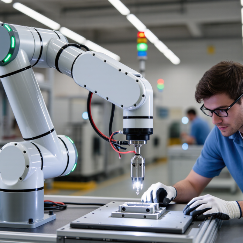
Table of Contents
[Hide]
Definition and Industrial Role of a Collaborative Robot Arm
A collaborative robot arm, or cobot, is an industrial manipulator designed to operate near people under defined safety conditions. Powered joints move a tool, gripper, or sensor along programmed paths. Depending on its design, the arm may detect contact, monitor force, limit speed, or stop when someone enters a monitored area. Collaborative does not mean risk-free. That matters.
In factories, cobots often handle repetitive tasks such as feeding parts into a fixture, tightening fasteners, tending a machine, or moving inspected items between trays. An operator might load parts while the arm performs a steady cycle, leaving more time for checks or setup. Some systems support hand guiding, so workers can teach a route by moving the arm. Features differ.
A cobot usually supports a work cell rather than replacing every human decision. Engineers choose its payload, reach, tool, and speed for the task, then assess pinch points, sharp edges, and unexpected motion. Extra safeguards may still be needed. A gripper can squeeze even when the arm moves slowly. Integration also takes adjustment: parts vary, fixtures drift, and a planned path may need tuning on the shop floor. That is easy to underestimate.
Related Posts
-
How to Choose a Collaborative Robot Arm in 2026?
-
China Top Collaborative Robot Arm Manufacturers?
-

Unlocking Creativity: How a Small Robotic Arm Can Transform Your DIY Projects
-

What is a small robotic arm and how does it work?
-
How to Choose a Small Robotic Arm in 2026
-
2026 Best Cobot Robot for Efficient Manufacturing Solutions?
Brands
Proudly Trusted by Top Suppliers Worldwide





Let us know and we will automate, together to fit your industrial needs.
 +91-97254 16844
Clients
Proudly Trusted by Top Companies Worldwide


Do you need Help? Get in touch.
X
Please fill out the form below and we will get back to you as soon as possible.