o p t i m a r o b o t i c s

Blogs

What Is a Universal Robot Arm and How Does It Work?

A universal robot arm is a programmable robotic system designed to handle different tasks across factories, laboratories, warehouses, and workshops. Unlike a fixed-purpose machine, it can change tools, movements, and production routines through software. A technician may guide its wrist by hand, attach a gripper, and teach a precise path within minutes. That flexibility explains its growing role in modern automation.

The International Federation of Robotics reported 541,302 industrial robots installed worldwide in 2023. Its World Robotics 2024 report also recorded more than four million industrial robots operating globally. These figures show strong demand, but they do not make every robot suitable for every workplace. Payload, reach, speed, safety functions, and integration costs still matter. A small universal robot arm may lift only a few kilograms, while heavier systems require guarded work zones and stronger foundations. The details decide the result.

Esben Østergaard, co-founder of Universal Robots, expressed the human-centered vision clearly: “People should work with robots, not like robots.” That idea captures the appeal of collaborative automation. Sensors can detect contact, while software limits force and speed near workers. However, safety is not automatic. Risk assessments, training, maintenance, and correct programming remain essential. A robot can repeat a bad instruction perfectly. That is the uncomfortable part.

This guide explains how a universal robot arm senses movement, receives commands, controls its joints, and completes practical tasks. It also examines real costs, technical limits, and common implementation mistakes. The technology is powerful, but not magical.
What Is a Universal Robot Arm and How Does It Work?

What a Universal Robot Arm Is and What Makes It Different

What Is a Universal Robot Arm and How Does It Work?

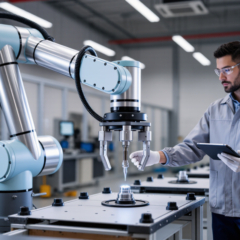
A universal robot arm is a programmable machine designed for many different tasks. It can move, pick, place, weld, inspect, or assemble parts. Its joints use electric motors, gear systems, and position sensors. A controller coordinates these movements through software. An operator can teach points, adjust speed, and change the end tool without rebuilding the entire workstation.

The word universal can mislead. The arm is not suitable for every job. Its real strength is flexibility. A fixed industrial robot may repeat one process at high speed, while a universal arm can move between smaller production tasks. It usually has a compact structure and several rotating joints. This helps it reach awkward positions beside a workbench. It may also use force sensing, which helps detect contact during handling or assembly. Not quite human-like.

In practical installations, setup quality matters as much as the arm itself. A technician must check payload, reach, cycle time, tool weight, and workspace risks. Safety features do not remove the need for guarding, testing, and worker training. The arm may appear simple after programming, but small errors can cause poor alignment or dropped parts. A practical lesson is clear: flexible does not mean effortless. Reliable performance comes from measured trials, clear procedures, and regular inspection. Universal robot arms are different because they can adapt, but their limits still require honest evaluation.

The Main Components and Joint Structure of a Universal Robot Arm

A universal robot arm is a programmable mechanical system built from links, joints, motors, and control electronics. Its structure often uses six rotary joints, giving movement similar to a human shoulder, elbow, and wrist. Each joint contains a motor, gearbox, encoder, and brake. Encoders report the joint angle, while the controller calculates position and speed. The arm’s frame carries loads, but the wrist needs precision. Small errors there can shift a tool by several millimeters.

The controller combines joint data with motion commands and sensor feedback. It can then coordinate the base, shoulder, elbow, and wrist as one chain. End effectors may include grippers, welding tools, or inspection cameras. According to the International Federation of Robotics, 541,302 industrial robots were installed worldwide in 2023. That figure shows strong demand, but it does not prove every arm suits every task. Payload, reach, repeatability, cycle time, and safety functions still require practical testing. A polished specification sheet can hide difficult cable routing or vibration.

Tips: Check the joint limits before selecting a tool. Measure the real payload, including cables and fixtures. ISO 10218 guidance supports risk-based robot integration, but site conditions remain important. In practice, a dry run can reveal collisions that software simulation misses. I have found that wrist flexibility is useful, yet excessive movement can reduce stiffness. That trade-off deserves honest review.

How a Universal Robot Arm Senses, Plans, and Moves

What Is a Universal Robot Arm and How Does It Work?

How a Universal Robot Arm Senses, Plans, and Moves

A universal robot arm is a flexible machine designed for many tasks, including assembly, inspection, packaging, and machine tending. Its value comes from adaptability, not unlimited ability. A typical arm uses joint encoders to measure position and torque sensors to detect resistance. Cameras or depth sensors can identify objects, edges, and changing positions. These inputs create a working picture of the robot’s surroundings.

The controller then plans a movement through software. It calculates joint angles, checks reach, and selects a safe path around obstacles. Inverse kinematics helps the tool reach a chosen point, while feedback continuously corrects small errors. If the gripper meets unexpected resistance, the arm can slow down or stop. This loop happens many times per second. In practical installations, calibration matters greatly. A small mounting error can produce inaccurate placement. The system may appear intelligent, but it still depends on clean data, stable fixtures, and careful programming. That limitation deserves attention.

Tips: Keep cables secured and sensors clean. Test slow movements before increasing speed. Confirm the payload, workspace, and emergency stop settings. Record failed motions instead of hiding them. They often reveal poor calibration or an unsafe assumption. A universal arm is powerful, but thoughtful setup makes it reliable.

What Is a Universal Robot Arm and How Does It Work? - How a Universal Robot Arm Senses, Plans, and Moves

System Area Measurable Dimension Representative Data How It Works Practical Significance
Robot Structure Degrees of freedom Six rotary axes are typical Each joint contributes one controlled rotational movement, allowing the arm to position and orient its tool in three-dimensional space. Six-axis motion can independently control position and orientation for tasks such as assembly, dispensing, and machine tending.
Workspace Maximum reach Approximately 500–1,800 mm across many general-purpose arms The combined link lengths and joint limits define the volume that the tool can reach. Reach must cover the work area while preserving clearance from fixtures, people, and other equipment.
Load Handling Rated payload Approximately 3–20 kg for many collaborative-style arms Joint motors and gearboxes generate torque to move the arm, tool, and workpiece within the rated load. The effective payload decreases when the load is far from the wrist or when the arm is fully extended.
Positioning Repeatability Commonly about ±0.02 to ±0.10 mm, depending on design and operating conditions The controller repeatedly commands the same joint positions using encoder feedback and calibrated kinematic models. Repeatability describes consistency at a known target; it is different from absolute positional accuracy.
Joint Feedback Position measurement Encoders measure joint angle and direction continuously The controller compares commanded joint angles with measured angles and corrects motor output when they differ. Feedback enables accurate motion, error detection, homing, and controlled stopping.
Force Sensing Contact and torque detection Motor-current estimation is common; six-axis wrist force/torque sensing may be added Changes in motor current or measured force indicate contact, resistance, or an unexpected load. Force feedback supports hand-guiding, insertion, polishing, compliant assembly, and collision response.
Vision Object detection and localization Two-dimensional cameras provide image coordinates; three-dimensional cameras add depth information Software identifies objects, edges, markers, or surfaces and transforms their coordinates into the robot reference frame. Vision allows the arm to handle variable part locations instead of relying only on fixed positions.
State Estimation Arm pose Calculated from encoder readings, link geometry, tool data, and coordinate transformations Forward kinematics converts joint angles into the position and orientation of the tool. A reliable pose estimate is required before the controller can plan or correct a movement.
Motion Planning Path and trajectory generation A path defines where the arm travels; a trajectory adds timing, velocity, and acceleration The planner selects collision-free joint or Cartesian movements subject to joint, speed, and payload limits. Planning determines whether a task is efficient, smooth, reachable, and safe to execute.
Inverse Kinematics Target pose conversion Converts a desired tool position and orientation into joint-angle targets The solver evaluates possible joint configurations and selects one that satisfies reachability and clearance constraints. Multiple solutions may exist, so the selected posture affects collision risk, speed, and joint movement.
Motor Control Closed-loop regulation Position, velocity, and torque control are used at the joint level Control algorithms continuously compare target values with sensor feedback and adjust motor commands. Closed-loop control improves stability and helps the arm respond to disturbances and changing loads.
Tool Interaction End-effector function Typical tools include grippers, vacuum devices, screwdrivers, welders, and dispensing heads The robot supplies position, orientation, force, and sometimes pneumatic or electrical signals to the attached tool. The arm is general-purpose, but the tool determines much of the task-specific capability.
Safety Response Protective monitoring Monitors speed, position, joint limits, force, protective zones, and emergency-stop inputs When a limit or abnormal condition is detected, the controller can reduce speed, stop motion, or remove drive power. Safety functions must be assessed for the complete application, including the tool, workpiece, layout, and operating procedure.
Programming Task definition Programs commonly contain waypoints, speeds, accelerations, tool actions, waits, and sensor conditions The user defines a sequence of actions through a graphical interface, hand-guiding, scripting, or external control software. Reusability of programs makes the arm adaptable to repeated production and changing workflows.
Overall Operation Sense–plan–act cycle Sensors provide feedback; software plans a response; motors execute the command The controller repeatedly updates the robot’s estimated state and adjusts motion while the task is running. This feedback loop is what enables a robot arm to operate reliably rather than simply replaying open-loop movements.

Note: The numerical ranges are representative values for general-purpose collaborative-style robot arms. Actual reach, payload, repeatability, speed, sensing, and safety performance vary by arm design, tool, payload position, installation, and application.

The Step-by-Step Process of Programming and Operating the Arm

A universal robot arm becomes useful only after its movement becomes a controlled sequence. Programming begins with a risk assessment, workspace inspection, and a clear task definition. The International Federation of Robotics reported 541,302 industrial robot installations worldwide in 2023. That growth increases the need for disciplined commissioning, not rushed teaching.

The operator mounts the arm, checks payload limits, and defines the tool center point. Then, the controller records the base, tool, and workpiece coordinates. Each waypoint should match a physical action, such as gripping a part or placing it inside a fixture. Keep speeds low during teaching. Use hand-guiding only when the system permits it. A dry run follows, with the gripper empty and nearby workers outside the safeguarded area. The operator then tests inputs, outputs, emergency stops, and recovery steps. Standards such as ISO 10218 and ISO/TS 15066 support this safety process, but they do not replace a site-specific assessment. Small errors matter. A loose fixture can shift the programmed path by several millimeters. In practice, the first cycle rarely runs perfectly. I would record every unexpected stop, refine the waypoint, and repeat the test before production. Preventive checks should include cables, joints, tooling, and software backups. The IFR’s World Robotics 2024 report also recorded more than 4.2 million industrial robots operating worldwide at the end of 2023, showing why reliable operation matters beyond one workcell.

What Is a Universal Robot Arm and How Does It Work?

A typical universal robot arm uses six independently controlled rotary joints. The joints work together to position and orient the tool in three-dimensional space. Programming normally involves setting the tool and payload, teaching waypoints, defining motion parameters, testing at reduced speed, and running the automatic cycle.

The chart represents the six rotational axes commonly used in a six-axis universal robot arm. Each axis contributes one degree of rotational freedom to the programmed motion.

Common Industrial and Collaborative Applications of Universal Robot Arms

What Is a Universal Robot Arm and How Does It Work?

A universal robot arm uses programmable joints, sensors, and end effectors to perform varied tasks. Its controller coordinates movement, speed, grip, and position. Vision systems can locate a metal part on a moving tray. Force sensors can detect contact during insertion or polishing. The word universal can mislead. No arm performs every task without careful integration.

Industrial Applications

Industrial applications remain broad. Arms weld frames, load machine tools, assemble components, inspect surfaces, and stack cartons. The International Federation of Robotics reported 541,302 industrial robots installed worldwide in 2023. Its World Robotics 2024 report also recorded about 4.28 million robots operating globally. These figures show mature demand, not effortless deployment. A poorly designed gripper can stop a production cell within minutes.

Collaborative Applications

Collaborative applications place the arm near trained workers. Typical jobs include screwdriving, packaging, quality checks, and material presentation. The Association for Advancing Automation reported 31,159 robot units ordered in North America during 2023. Safety still depends on risk assessment, speed limits, workspace design, and proper training. Collaborative does not mean harmless. In practice, cycle-time pressure can encourage unsafe shortcuts, which deserves more attention.

Successful projects begin with a small, measurable task, such as moving one component every twelve seconds, then expand after testing.

Brands

Proudly Trusted by Top Suppliers Worldwide

Let us know and we will automate, together to fit your industrial needs.

Clients

Proudly Trusted by Top Companies Worldwide

Do you need Help? Get in touch.

X

Please fill out the form below and we will get back to you as soon as possible.

    Subscribe our newsletter & get updates